
New value gear for a DJH Caprotti Standard 5
The valve gear of my long-suffering DJH Caprotti Standard 5 fell off. The first time both sets were glued back on.
The second time it was convenient, and for time it travelled around with both Lost Wax castings popped into the tender bunker, which made it look rather a loco heading for Barry Scrapyard.
Then about a month ago I had big layout declutter, and popped it in a box to keep it safely out of the way. Suffice to say in the process the driver's side gear had gone missing.
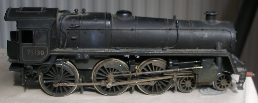
Here is the fireman's side showing what should look like!
The scan was mirrored to represent the missing driver's side gear.
Although on one level it is a simple casting, it involves a number of twists and turns, and the box that fits over the centre axle. It seemed like a job well-suited to my recently acquired 3D gear.
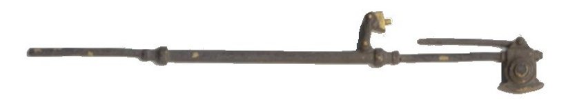
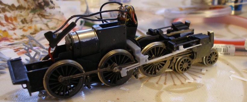
The first thing was to place the surviving Lost Wax casting in the scanner. As the photo below shows, this would have sufficed, but it was clear that detail had been simplified. A trawl of the Web located a suitable photo of 73129 at Butterley, from which the gear could isolated and then scaled to match the scan of the Lost Wax casting.
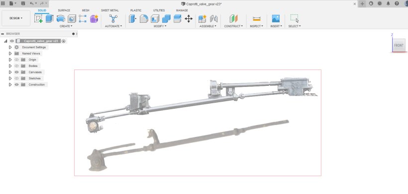
The CAD software Fusion 360 allows the importation of drawings or photographs as 'canvasses', and these can then be 'scaled' once loaded. You just need to know one dimension.
The software then allows a 'sketch' to be created on top of the canvas, as shown below.
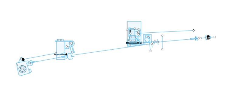
The tubing and rods making up much of the gear is shown as a straight line. Fusion has a pipe tool which generate 'pipe' of the appropriate diameter.
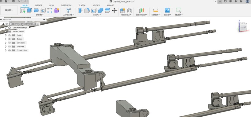
One side, as per the canvas, was drawn initially, and then the 'mirror' tool was used to create both sides as a single unit. In this version the whole gear is drawn out, as consideration was been given to replacing all the DJH castings.
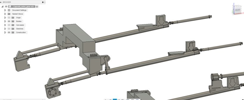
However, a more critical examination of the loco suggested that the casting represented a firm second fixing point for the new gear, and the drawing was modified accordingly, with two small platforms to glue beneath the existing casting created. This was a shame as the detail as created in Fusion was rather nice, although as will be seen, probably irrelevant.
The file created in Fusion 360 was loaded into the Chitubox slicing software. This clever software allows the model to be orientated in two planes, so that it prints at a jaunty angle on the printing plate. It also #layers' the model, as the 3D resin printing process prints a layer at a time to build the complete model. There can easily over a thousand layers in any model, and this is why the print times can be quite extended. In this it was three and a half hours, so time to set the thing running and pop to town to do some shopping.
And this is the result some fours later.
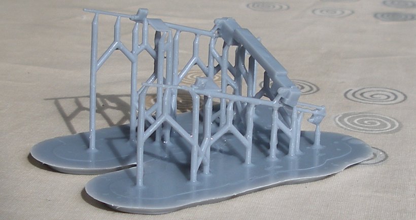
The resin print has to be removed from the steel printing plate, and then washed in IPA to remove the residual liquid resin. The resin is not nice stuff, and great care needs to be taken not to get it on the skin. A Elegoo (other brands available) curing and washing station is highly recommended. The item has been washed in IPA in the washing station, and rinsed under the tap to remove the IPA.
At this stage it is quite flexible, and this a good point to remove the base and scaffolding.
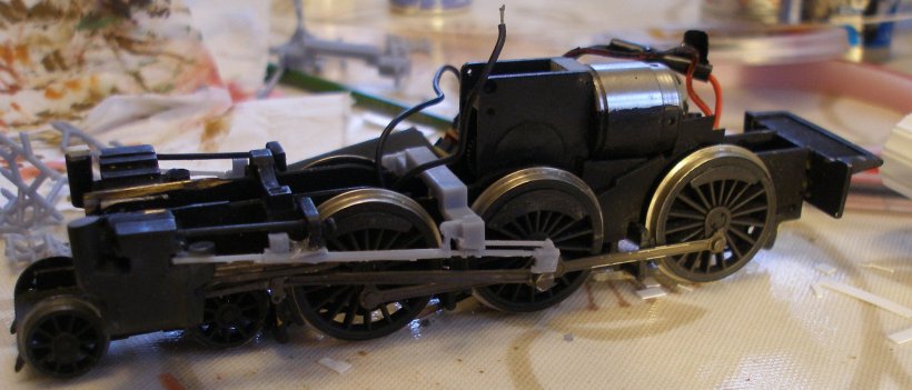
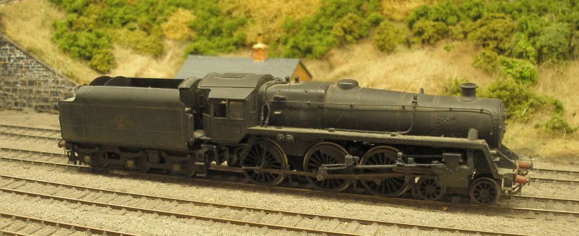
And now in Blue Peter 'here is one I made earlier' style, is the gear now fitted to the loco. There were in fact four iterations of the gear, so from start to finish the printing actually took over 12 hours. It took a couple of prints to accurately judge the clearances needed for the connecting and coupling rods
As a tip, I tend to do initial designs in the evening, and then print over night. In the morning the model can removed, clean-up and trial fitted first thing, and then any modifications made to the design and the printer started again. This leaves the rest of the day clear for other stuff, so making use of your valuable time. A key part of the design has been to replace the three DJH components with a single unit. Note the wire from the pick-ups that has helpfully detached itself from the DCC socket.
And as it appears on the fireman's side.
And now it is just a matter of re-soldering the errant wire, painting the gear and popping the body back on.
In the Fusion 360 drawings it was possible to represent the Universal joints accurately, but this nuanced detail is too fine to show effectively, and so the 3D printed result is very similar to what DJH originally provided.
If you have got this, and the reason is that you have also lost all or some of your Caprotti gear, then drop me an email at the address below and I will supply you one at a very reasonable price :-)

Copyright J K Wallace, t/a 'Hall Royd Junction' 2013-2023 email: Hall Royd Junction
7 Portobello Close, Chesham, Bucks. HP5 2PL, UK
tel: +44 (0)7513 412880