
<<< Baseboards for Hall Royd Out-of-the-box Working Semaphore Signals >>>
Flipping Baseboards
The boards were successfully transferred to the loft, legs fitted and all clipped together. Only one board had two sets of legs, each subsequent board having one set of legs, with the non-leg end being held up by the leg-end of the adjacent board.
To pull out a board to work on required a set of temporary legs to be fitted to the adjacent board, using the pockets provided. Downstairs with only one or two boards erected at any given time, this had worked well, there being plenty of room to lie the board on its side to fit the legs in the pockets, before turning the board right way up, to stand on its legs.
However pushing the boards apart and then rotating them to remove the legs in the confines of the loft was highly frustrating, such that in the last few months no work was being undertaken underneath...which meant no work was being undertaken.
A rethink was clearly required.
The solution was to create a sub-frame of 2" x 1" of Wikes' finest kiln-dried timber at £9.96 a pack. The uprights were screwed directly to the roof trusses , and then the horizontals, parallel and directly under the plywood sides, were attached to the top of the uprights directly under the boards in situ. Finally cross bearers were inserted at 18" centres.
Having put off this obvious course of action for some months, it only took 2 hours to complete a 15' x 2' frame.
copyright J K Wallace, all rights reserved
But what a difference. Firstly, the area under the layout is now greatly simplified, so that its a lot easier to get underneath. But crucially it now only takes seconds to unclip the adjacent boards, push them apart and then lift the board to rest on its side. Working on the underside is now greatly simplified.
One small problem has been a tendency for the centre of each board end, where the boards meet, to bow, so that the rail ends have moved apart resulting in a wider gap.
Plan A was to place a baseboard connection clip under the boards at the joint, as well as a pair on the sides. However the need to push the boards along the framework to separate them meant that anything projecting below the boards now caught the cross-bearers.
The solution has been to dig out the bolts and wing nuts which it was thought had been finally retired with the old layout. A single hole was drilled through the ends, and a bolt inserted and tightened. This has neatly drawn the adjacent boards together and closed any gaps in the rails. As they are not used to align the boards, this does give a very solid connection.
I may yet fit some slim-line handles to the sides, as it is difficult to get a purchase when the board is directly aligned with the sub-frame, but as of now the boards can be flipped with much greater ease.
This development has allowed the point control system to be completely replaced; click here to read how.
Posted 11 September 2013
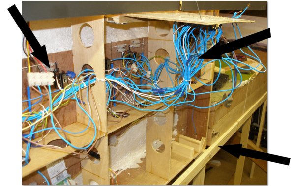
Original DC wiring for point control. Once the manual rod system was adopted this wiring was removed.
The sub-frame assembly on which the boards now rest. The socket for the legs can be seen in the corner of the upturned baseboard.
Copyright J K Wallace, t/a 'Hall Royd Junction' 2013-2023 email: Hall Royd Junction
7 Portobello Close, Chesham, Bucks. HP5 2PL, UK
tel: +44 (0)7513 412880