
Tale of a Hornby Rebuilt Patriot 'spares or repair' - 1
Much turns up an eBay in the 'spares or repairs' category, and I have recently wanted to increase the fleet of Jubilees. The latest Bachmann offering is now pushing the £140 mark, and I was seeking a cheaper solution. On eBay I spotted a Hornby Rebuilt Patriot chassis that was in a severe state of distress, but - with an immaculate tender - it seemed worth a punt and the final bid was £21.
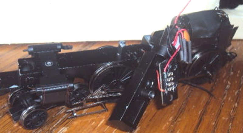
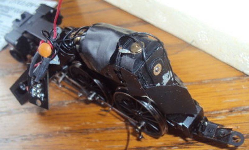
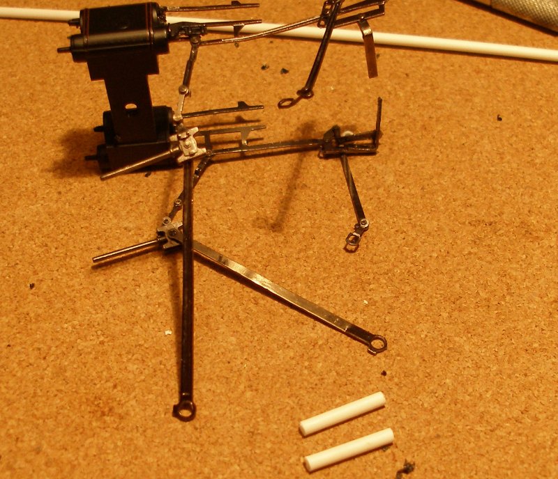
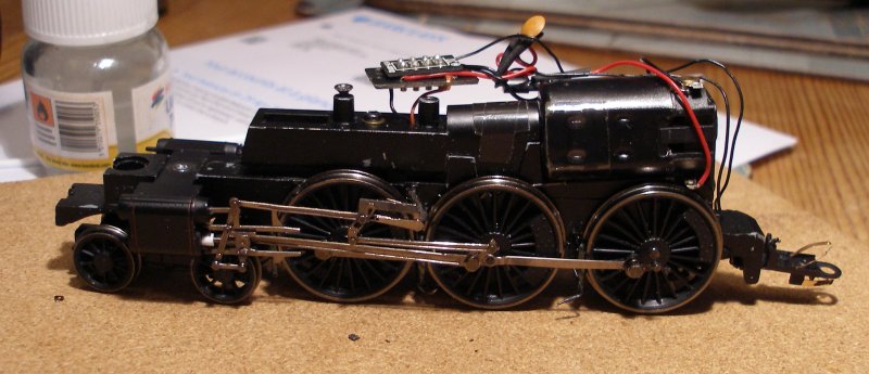
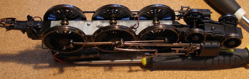
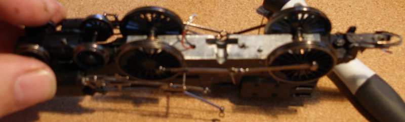
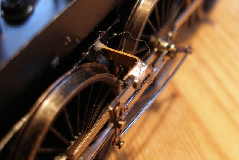
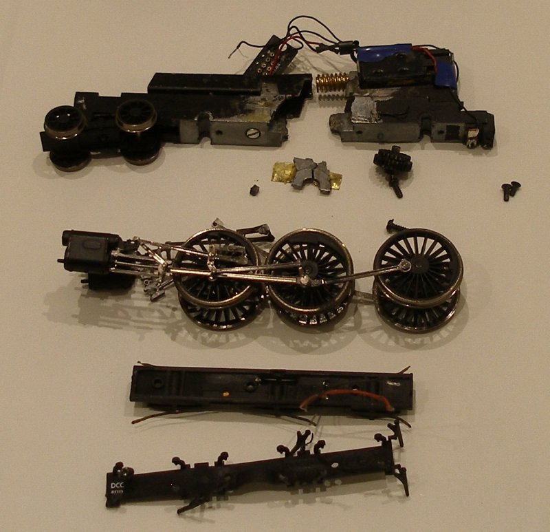
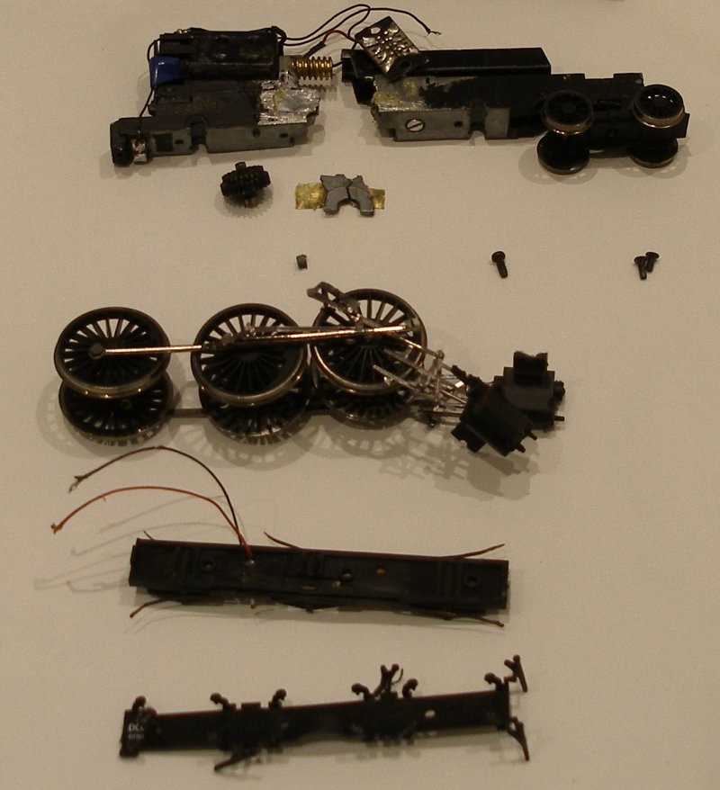
As can be seen from the to images below, the chassis had suffered some form of catastrophic failure, with the valve gear having become disconnected from the cylinder block, and the lower keeper plate removed such that the pick-ups were still soldered to their wires, but not retained in any other way. A quick application of power showed that the motor turned easily but the gears were not meshing.
I have had the gear meshing problem with a Hornby 'Britannia', and this seemed an excellent opportunity to establish the cause and find a resolution.
The first move was to identify how the various bits fitted together, and the extract from the Hornby exploded diagram below shows the two areas of concern. Clearly the crossbars had to refitted to the cylinder block, and secondly, the casting that held down of front of the motor seemed to be loose, and this appeared to be the reason that the gears were not meshing. A trawl of the various forums showed that this casting is an issue on a number of Hornby models, and in particular the T9. In the case of the T9 it appears to fracture, and is not offered as a spare.
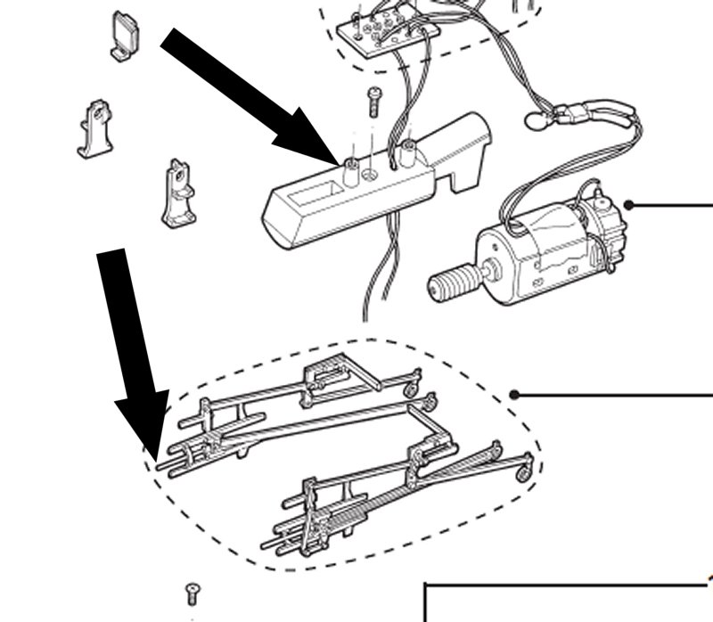
First the slide bars were superglued into the rear of the cylinder block, as I have found before that once they are removed, they are never a tight fit subsequently, and have a distressing habit of disassembling themselves. Secondly, the casting on the top of the chassis needed to be more tightly secured, and this was achieved by inserting a washer on the screw so that it could have a firmer purchase, and so hold the casting more tightly against the chassis block. We were now ready for the first powered test run on the work bench.
A quick burst of power, and the crosshead on the fireman's side was forced down, pushing the lower slide bar out of alignment. It seemed that the piston rod was actually too short (or the cylinder block to far forward), and it was actually coming clean out of the block when the crankpins were at their furthest point of travel. The simplest route seemed to be to make a guide for the piston rod out of a piece of plastic tube. First the existing holes in the cylinder block were drilled out, and the resulting holes can be seen in the image below.
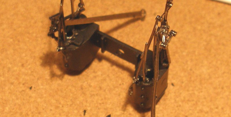
The two 'liners' can be seen below, awaiting insertion into the new holes drilled into the cylinder block.
The image below shows the new liners glued into place, and proud of the rear face of the cylinder block.

A new lower keeper plate was required, and this was fashioned from a spare Black 5 one I had. This needed to be cut, with the front section glued to the lower plate. The brake blocks needed to be shaved slightly with a scalpel, as the Black 5's wheels are smaller that those on the Patriot/Jubilee/Scot.
The valve gear was now reassembled...
The collar is first placed over the crankpin, and then the connecting rod added. Finally the return crank is added and the crankpin screw fitted. This needs to be screwed in gentle, and the return crank has to engage with the slotting cut into the end of the cranpin, and allows accurate retention of the return crank. With the crankpins at the bottom of their travel downwards, the return crank should be set roughly 10 degrees from the vertical facing the front of the loco. By gentle rocking the crank forwards and backwards will allow the crankpin to engage with the slotting. Once engaged, tighten the crankpin screw fully.
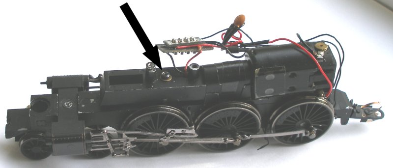
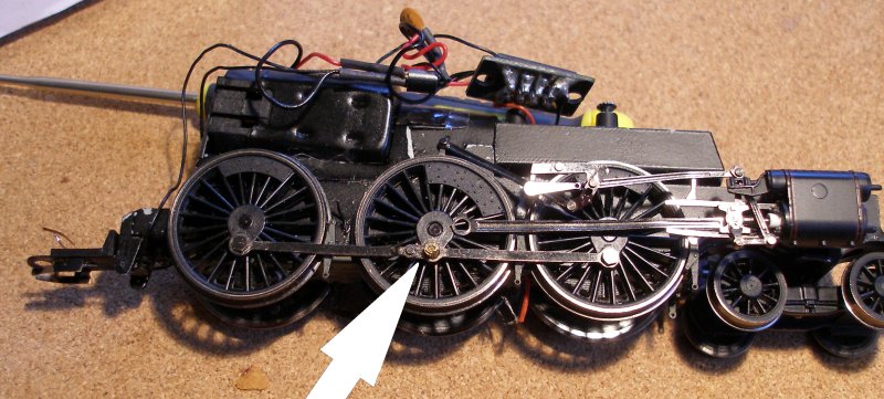
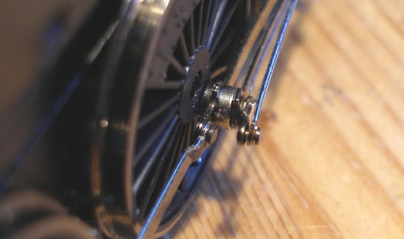
And then an Whoops moment. On screwing the crankpin screw back in on the fireman's side using the trusted nut spinner, the screw sheared. As can be seen with the white arrow below, the screw sheared inside the shank, and so could not be unscrewed. The only solution appeared to be to order a replacement set of driving wheels and crank pin screws from Peter's Spares.
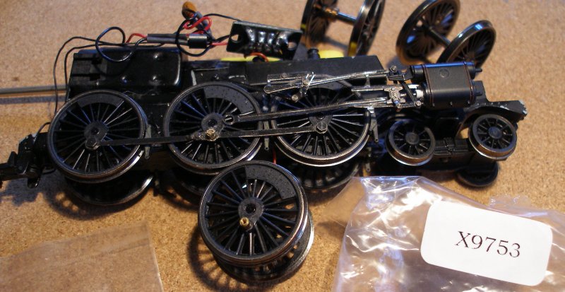
This coincided with the weekend, and some prompt packing and wrapping by Pete's Spares saw the replacement parts promptly delivered for the Monday. Note the part number X9753, with the squared ended balance weights as applied to the 'Patriots' and Jubilees': the 'Scots' had crescent shaped weights.
The switch over was very straightforward. First, the keeper plate is removed by unscrewing the three cheesehead screws.
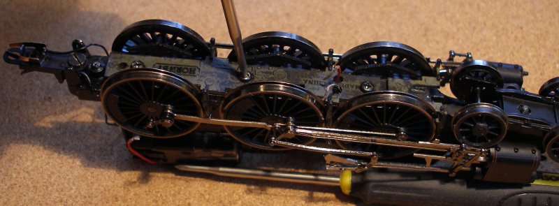
The keeper plate is lifted out of the way (note, the pick-up wires have been unsoldered from the pick-ups).
The remaining crank pin screw was removed from the centre wheelset, and the rods gentle levered away to allow removal.
The new wheelset pops straight in/

The collar goes between the coupling and connecting rods.
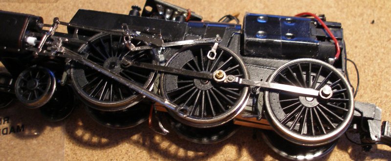
All back together again!
This view shows how the collar sits, with the connecting rod on the outside. I did try it the other way round, but this is the better position.
Having been test run on the bench again, it is time to start fitting the new pick-ups. Although the original phosphorus bronze pick-ups had survived, they did not look particularly sturdy, and I opted to replace them with my standard arrangement. This involves superglueing paxolin sleeper strips to the keeper plate, such that the screws are still accessible.
The new pick-ups are formed from Gibson 0.45mm straight wire.
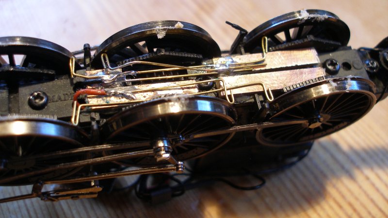
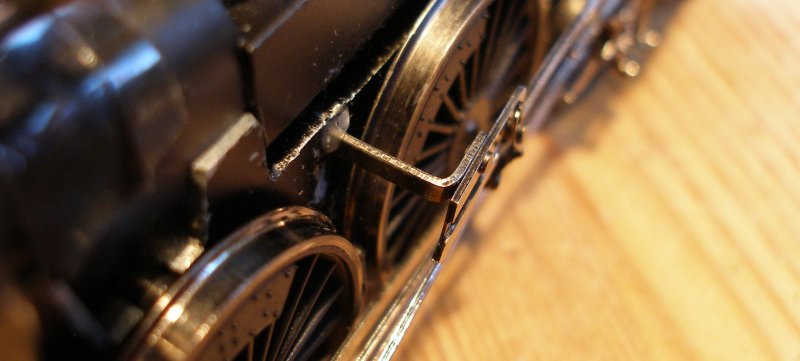
I had not been very impressed with the way the motion bracket was attached to the chassis. For the Black 5 this had been a proper bracket actually screwed to the chassis block, but in the Patriot it is a push fit into a slot cut into the block. Suffice to say this was a loose fit, and as the motion had bowed out due to all the handling, this was not providing much support, and it had been my intention to glue it into place. However, before that could be done, it fell off. A new bracket was created from scrap brass fret. The motion and the end of the new bracket were tinned, the bracket glued into place, and when the glue had set, a touch of the hot iron neatly welded the to pieces together.
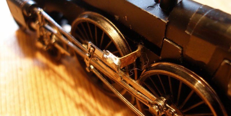
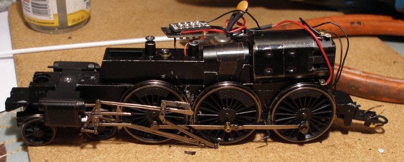
For comparison, this is what the original, unmodified side looked like. This has also been glued into the chassis.
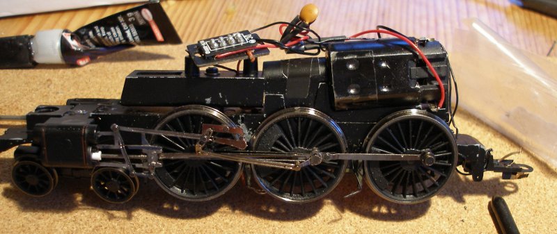
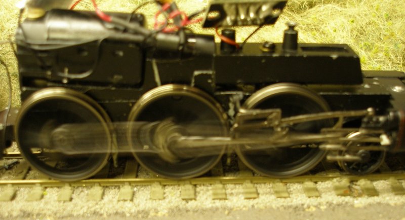
Now with pick-ups and the motion fully re=assembled, it was finally time for a road test!
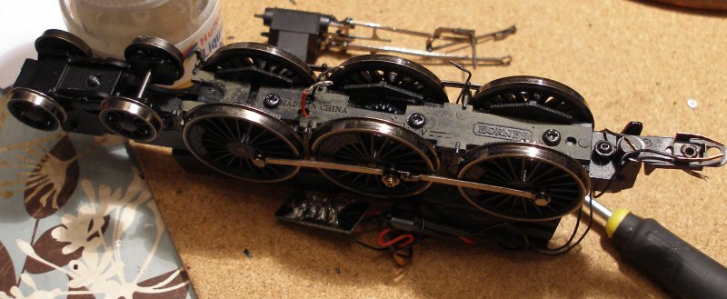
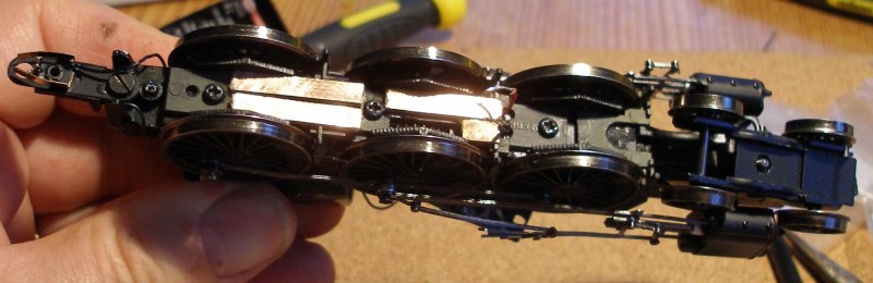
I had also acquired a Bachmann 'spares or repairs' chassis and it is now possible to compare the two side-by-side.
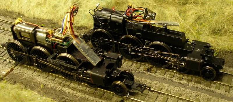
First impressions are that the Bachmann chassis has a nicer finish, and the mechanism runs that little bit smoother. It also seems to have better track holding characteristics. I still have to check the Hornby back-to-back, but I seem to recall that the Hornby back-to-back is 14.2mm whereas Bachmann works to the standard 14.5mm measurement.
A key point to note for anyone tempted to switch bodies is the location of the motion bracket casting. On the Bachmann chassis (nearer) it is integral with the chassis, whereas Hornby have it hanging from the underside of the footplate
The final - unscientific - test was prompted by a remark that Churchward allegedly make to the GWR board when questioned as to why the L&NWR could build locomotives more cheaply that the GWR at Swindon. Churchward is supposed to have said that one of his could pull two of theirs backwards. So the two chassis were placed on the track back-to-back, and 'reverse' and 'full speed' selected for them. With both sets of wheels freely spinning, I am afraid to say that the Hornby chassis comfortably pushed the Bachmann one backwards - and at a reasonable speed to boot!
Tale of a Hornby Royal Scot Patriot 'spares or repair' - Part 2
Having rescued one, it seemed worthwhile keeping a look-out for similar 'distressed' locos.
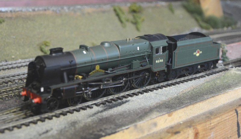
This was the next lot to catch my eye:
"I am selling a Hornby 7P Royal Scot Class Locomotive No 46146, The RIfle Brigade, on a SPARES OR REPAIR basis. The Hornby model number is R2630 and the sale includes the original box which is in good condition. The problem with this engine is ( I am told) that the casting that holds the engine in position has split. This results in the motor disengaging with the drive gear. One can hear the motor working smoothly but the engines goes nowhere. Sometimes the engine moves in one direction but there is no consistency. The model has been little used but, as stated, it is sold on a SPARES OR REPAIR basis."
Closer examination showed the casting holding the front of the motor down, was, in fact, not broken, but none the less, the motor rarely engaged with the intermediate drive gear.
The motor bracket at the rear of the motor was loosed, as was the casting, and the motor gently lifted out, with the wiring intact. The base of the motor and the top surface of the motor mounting bracket were carefully cleaned - particularly the front section of the motor mount where the front of the motor sits. Both surfaces were then thinly coated with Thixofix (the stuff bought from hardware shops in tins), and then the to brought together after 10 minutes. The rear motor bracket was re-fitted and tightened up. A G-clamp was then used to firmly secure the motor against the motor mounting bracket (checking that the worm was properly engaged with the gear wheel). The chassis was then put to one side for 24 hours to allow the glue to fully cure.
A quick test with the DC wander leads proved the loco appeared to be working, and a DCC decoder was popped in and the body replaced. Unlike 46127 (see below), the body popped back on very easily, resulting in one fully restored loco. This 'glue technology' approach means that stripping down the loco at a later date may be tricky.
I now felt I was on something of a role, and thought the glue technology could be applied to something a little more adventurous....
Tale of a Hornby Royal Scot Patriot 'spares or repair' - Part 3
Having thought I'd got the hang of repairing the Hornby Scot/Patriot chassis, I have been keeping an eye out for further locos that could be successfully rescued.
The next one that presented itself was described as having a two-part chassis, with the chassis have cracked along the centre axle hole, thus:
"This Loco is Sold as Seen. The chassis have broken in the centre due to a fault during the manufacturing process. The collection of parts as received in the mail is shown below."
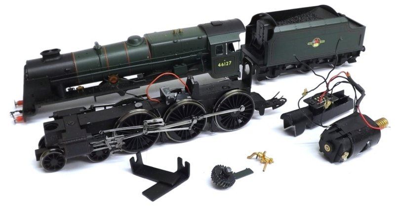
The loco was dismantled into its component parts. Everything was in good order with the exception of the chassis block and the casting which carries the DCC socket and holds down the front of the motor.
In the case of the chassis block, this had broken in an area immediately behind the centre axle hole, so the chassis was in two parts. A small amount of the chassis block that aligns the intermediate drive gear was missing, but the stub axle seemed to still seat well. There had obviously been problems with the casting with the DCC socket, as this had apparently been Araldited to the chassis block - this is apparent in the above image immediately above the front driving wheel.
The repair steps were as follows:
1. Chassis stripped down and all parts removed. The motion brackets are glued in, and where difficult to remove. The force required broke the cylinder block bracket (where it is screwed to the chassis block), and also one of the connecting rods became detached from the crosshead.
2. The two halves of the chassis block were glued together using Loctitie Superglue Gel, and pressed together on a flat surface until the glue had gone off (approx 10 minutes). The chassis was left over night.
3. Two oblong sections of old fret were cut out. These were trimmed to provide a patch over the crack on both sides of the chassis. The paint was filed off the chassis and the brass patches stuck on with long-setting Araldite. Again, the chassis was left a full 24 hours.
4. Once the glue had fully set, the brass patches were cleaned-up and reduced in thickness with a file. Any residual glue was cleaned out of the centre axle boxes.
5. The motor and intermediate gear wheel were test fitted, with the casting also put in place. It was apparent that the casting wasn't pressing the intermediate gear ale fully down, and two small squares of polystyrene sheet were glued to the bottom of the casting to hold the gear axle in place.
6. The motor rear mounting bracket was loosened, and then the motor glued to the mounting block with Thixofix (the full strength stuff in tins), and the rear bracket affixed. To ensure optimum positioning, the assembly was clamped with G-clamp.
7. The DCC socket casting was carefully cleaned up, and this was also glued in place with Thixofix (as the screw hole had been filled with Araldite). This would have been glued anyway, as the use of a single screw to secure this casting is inadequate to hold the motor in place. This was also clamped. The whole assembly was again left for 24 hours before the clamps were removed.
8. The connecting rod was re-secured to the crosshead. The cross head pin was drilled out from the rear, and a PECO track pin inserted. This was secured with Superglue on the front face and the excess cut off. The motion brackets would not fit back into the slot cut in the chassis block. These were slightly shortened to get a good fit and then superglued back into place, as the wheels and motion were placed back in the chassis. The pickup and lower chassis plates were fitted and screwed back into place.
9. As can be seen, the wiring was in place, but had been cut to allow the parts to be separated. This was now pieced back together and soldered. The connections to the tender coupling had to be tested to ensure the wires had been added correctly.They hadn't!
10. And finally the road test. A DCC decoder was plugged in, and the tender attached. It ran smoothly and quietly on first try.
This is a horrible bodge, but detailed here as the cracking of the casting or the chassis block appears to be a surprisingly common fault, and spares for both items are not available. This fault also seems to affect the Hornby A4. The key is the accurate fixing of the motor, and I have now used the Thixofix treatment twice with great success. Other people have suggested silicon, which I suspect this works just as well, but I prefer Thixofix as it is possible to accurately apply a thin coat to the arts to be glued.
The worst part of this repair was trying to put the body back on, although a spare Hornby unrebuilt Patriot body I have fits perfectly!!
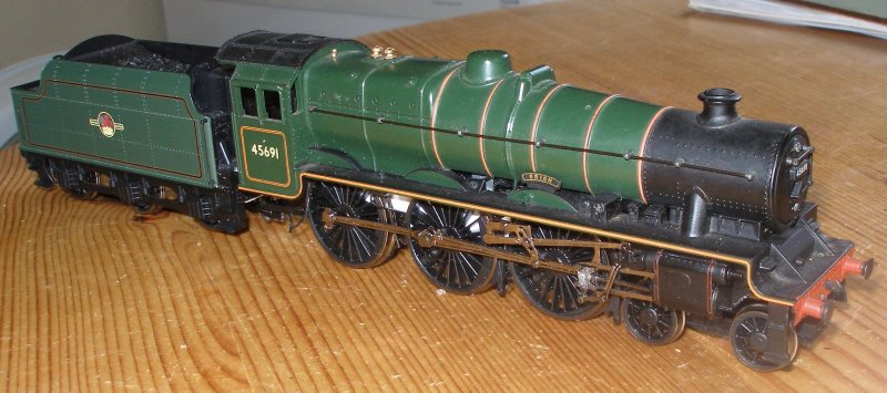
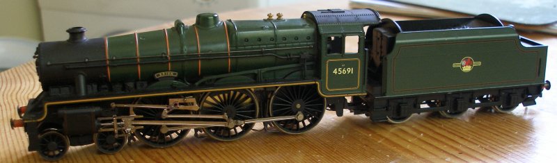
However, what we needed was more Jubilees, and a chance glance on eBay found a surplus original Mainline 'Orion' body. This almost slipped straight onto the chassis. The only adjustments were the removal of the original Mainline screw fixing behind the front buffer beam, and snipping off a protrusion on the front section of the Hornby chassis. Literally less than four minutes work produced a Hornby Jubilee. All it needs now is a motion bracket casting, and some cab steps.
Well...it did work, and work well. But a couple of weeks ago the intermediate gear wheel started to slip again. A critical examination showed that the metal on either side of the hole for the intermediate gear wheel axle had disintegrated.
The conclusion must therefore me that 'mazakrot' is an on-going process and that repairs may or may not permanently deal with it.
It was also apparent that the attempt to Thix-o-fix the 'casting with no part number' had failed, and could also be more effectively fitted. A hole was drilled though the hole for the pick-up wires, and then upwards through the basting. The hole at te keeper-plate end was rebated, so that a 6 BA bolt could be inserted flush with the underside of the chassis, and then the nut was applied above the casting. This was actually very effective, and properly secured the casting. The bolt can be clearly seen on the underside of the broken chassis in the photos below.
Unfortunately the chassis repair then failed, and I discovered that the chassis block on either side of the original crack had also disintegrated.
The following photos show the chassis - and to help other with similar issues - the original 'Old Comtemptables' body.

Copyright J K Wallace, t/a 'Hall Royd Junction' 2013-2023 email: Hall Royd Junction
7 Portobello Close, Chesham, Bucks. HP5 2PL, UK
tel: +44 (0)7513 412880