
Route Learning Car DE 320765
The Calder Valley main line, and the line over Copy Pit, really came into its own on Summer Saturdays when a procession of excursion trains left a wide variety of Yorkshire towns to head to the Lancashire seaside resorts of Blackpool, Southport and Morecambe. At Hall Royd Junction trains there was a choice of routes, although the more common route for the excursions was over Copy Pit and so to Burnley, Blackburn and Preston. At Preston they could pass though Preston and so onto the lines to Blackpool, or they could take a left turn at Todd Lane Junction and head for Southport along the coast.
Trains staying with the L&Y main line could be routed towards Bury at Castleton, just after Rochdale. At Bury they could turn right and head for Accrington, and join the earlier route to Preston, or they could carry on straight through Bury to Bolton, and then be directed to Southport via Wigan or towards Preston and Blackpool at Lostock Junction.
It will be apparent that with a multiple of starting points coupled with a surprising number of alternative routes and destinations which were only accessed for a relatively small number of Summer Saturdays each year that loco crews were going to need a lot of training, particularly at the start of each year, ready for Easter.
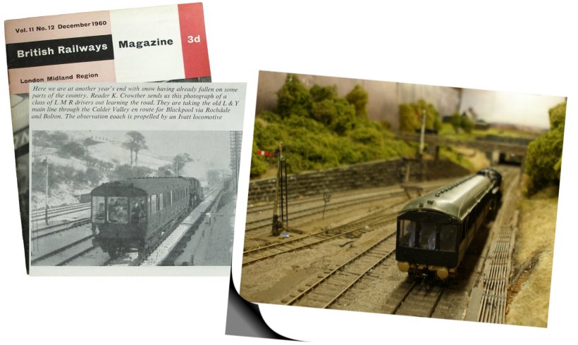
The 'British Railways Magazine London Midland Region', Volume 11 Issue 12 dated December 1960 featured a photo by railwayman K Crowther from the steps of Hall Royd Junction signal box showing loco crew training in progress. The York Motive Power Deport route leaning coach is shown being propelled Up the L&YR main by an Ivatt Class Mogul. The caption suggests that it contains LMR drivers out learning the road, travelling to Blackpool via Rochdale and Bolton. It is assumed that the photo was taken in the early months of 1960 (snow on the ground), and that K Crowther was the signalman on the day.
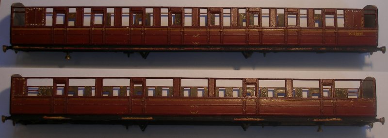
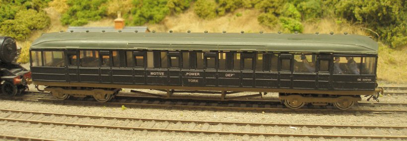
Clive Mortimor on the RMWeb group has noted that a photo of this carriage appears in Backtrack Volume 10 No. 4 dated April 1966 on page 184. This shows a Gresley teak vehicle numbered DE 320765 and lettered MOTIVE POWER DEPT, YORK on the side. It sports a yellow end. The photo is dated 6 August 1965 and the car is being propelled by Fairburn tank 42204, at, err, York Station.
As the photo is black and white, it would be easy to assume that the livery was a faded maroon. However David Ford has located a photo of the carriage in his father's collection showing it being pulled by a Class 46 in the down direction at Pilmoor which is posted on an RMWeb thread. The photo is dated April 1968 and the carriage is painted matt black, with yellow warning panels. The 'control trains' formed of Gresley stock that existed in the 1960s are also reported to have been painted black.
I am very grateful to Garry Hall for permission to reproduce his photograph of BR Standard 77012 at York with the Route Learning Car. All the photos I have seen of the carriage in operation with steam, shows the loco facing forward when propelling, and on that basis it is quite likely 77012 is readying for such a trip. Garry records 77012 was a York-based loco, which begs the question where she might had roamed whilst on route learning duties.
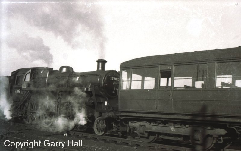
Hugh Llewllyn suggests this is a GNR Gresley 52'6" First Saloon No.807 built at Doncaster 1912, which became LNER No.4807 and was refitted as an Engineer's Saloon, BR No.DE320765 as pictured at York Shed, 07/67, although the coach is clearly on a 61' 6" underframe. The photo on Wikipedia shows it with Gresley compound bolster bogies.
The paperback edition of Michael Harris' 'LNER Carriages' hoiwever shows this to be a standard LNER Diagram Book (Dia 23). For those interested in modelling this car, there is a kit in the old Cooper-Craft range, or one of the new Hornby carriages. The livery appears to be Engineering Department black. The car also appears to be double-ended, so allowing training runs in both directions without having to turn it.
This is a delightful cameo, and it is reasonable to assume that it was kept pretty busy covering these holiday specials.
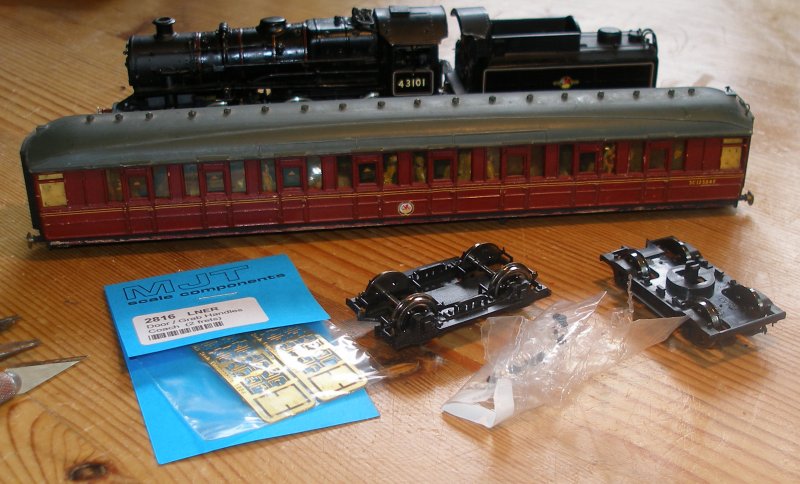
In the BR Magazine the loco isn't identified, and I have decided to provide 43101 which was then shedded at Wakefield, which seems as likely as any for a point of origin. In my freelance modelling days I bought a ready-built Millholme Ivatt in plain black. The open frame motor could not be easily converted to DCC, and this was replaced by one of the 1218 RG4s. The loco was renumbered as Wakefield's 43101. Having sorted the loco out, it was time to turn to the coach.
The parts acquired were:
1. A previously assembled Ian Kirk 3rd Compartment vehicle without bogies (from eBay)
2. A set of the current Hornby Gresley bogies from Peter's Spares
3. A set of MJT LNER door handles and grab handles from Dart Castings
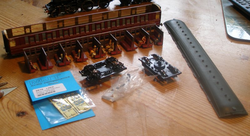
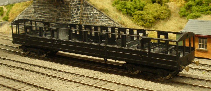
From careful study of the available photos, the seating seems to formed of station waiting room benches mounted on a series of raised steps. The Hall Royd photo shows 10 'jolly' drivers in various posses draped across the benches. The closest 'fit' appeared to the green plastic Merit-type, and two sets of seated loco drivers were also bought.
And this is how I did it...
I was sorely tempted to 'restore' the Ian Kirk, as it was a nicely assembled kit, but as a certain amount of work was required, I concluded it would be just a easy to proceed with the conversion. The Hornby bogies are nicely made models, but note the bag of 'bits' these seem to the parts of the springing (very apparent in prototype photos) which have clearly fallen off the bogies and were loose in the bag. These were carefully gathered up for refitting.
The first step was to remove the roof, which has sensibly only been glued at the ends. The interior had been glued in, but the joint had failed, and it was easy to lift out.
The corridor connections came off relatively easily, and the rouge edges created by the glue removed.
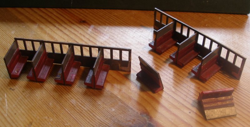
Only half the original interior is required. It is assumed that the middle four compartments were retained either for staff not directly involved in the route learning process or for when the route learning had finished for the day, and drivers wanted somewhere more comfortable to sit as they headed home. (It is not known where the guard might have travelled). The central double seat was removed (it was only glued to the corridor partition), and then the corridor partition vertically scored and then bent until it snapped neatly on the score line. The single seat unit was removed from the end of the surplus unit, and in the above shot, is ready to be fitted to the shortened seating unit.
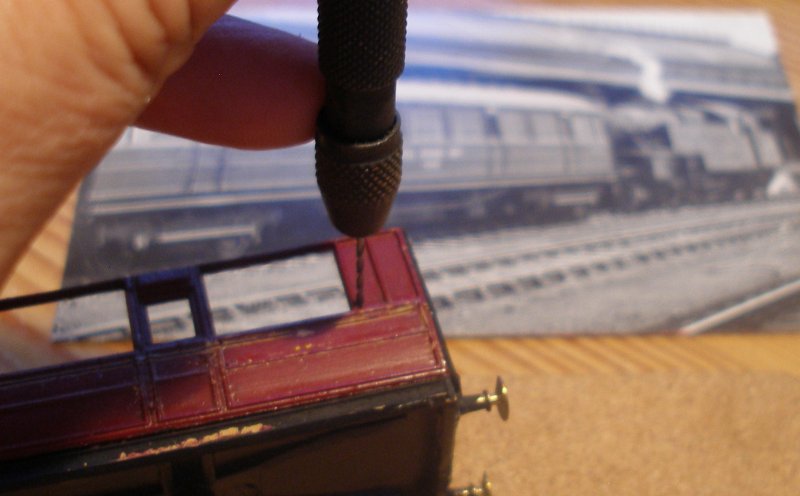
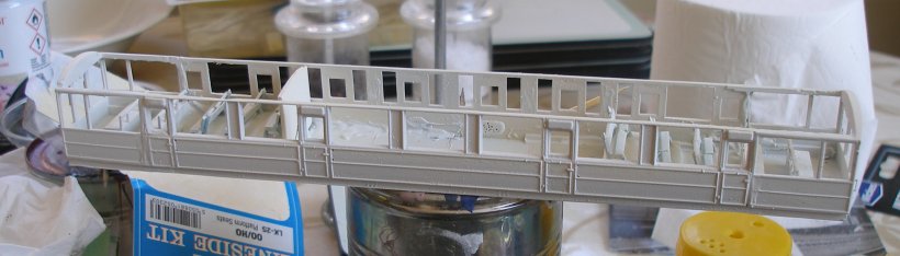
The end panelling on the corridor side has to be removed. This is done by drilling a series of holes around the panel before cutting out with a sharp scalpel.This is the first hole being drilled...
Great care is needed drilling the holes, and in particular along the top edge, taking care not to damage the adjacent window frame top rail.
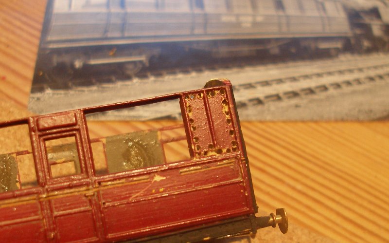
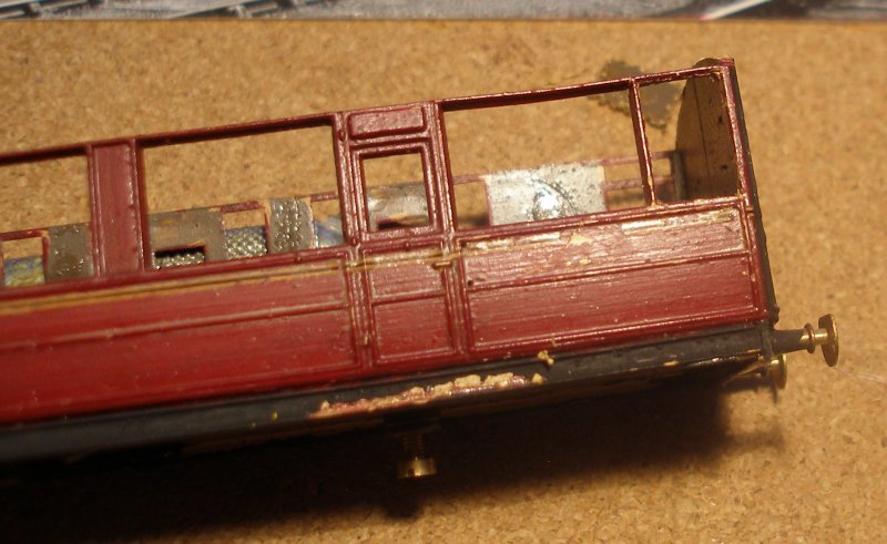
Finally, with a brand new blade, the holes are joined up, and the panelling removed. Great care was taken with the top edge, with the work being carefully supported whilst gently cutting/sawing.
25 August 2016
This photograph shows all the panels that need to be removed now drilled, but still in situ. The horizontal glazing bars in the windows at the ends also need to be removed, but I've left them in place for now, thinking it will give a little extra strength during the cutting out phase. For the avoidance of doubt, on the compartment side, two openings are going to be formed. So looking to the right of the coach side in the upper image, the first three panels next to the door will form one larger window, and the glazing bar will be removed from the surviving original window, so that the ends of the vehicle will be identically configured on both sides.
26 August 2016
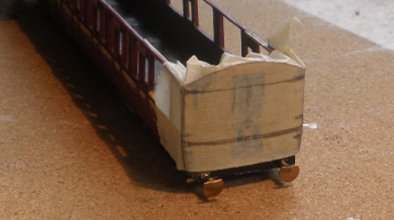
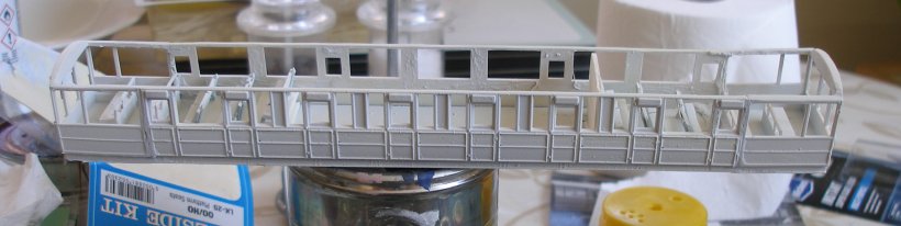
The next stage is to form the end windows. Masking tape was affixed across the end, and then the windows marked out. A series of holes were drilled round the three window frames using a pin vice.
5 August 2016
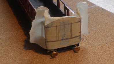
With the ends marked up, the areas to be cut were first drilled out using a manual pin vice, and then the holes gentle teased out into a cut using a new scalpel blade.
The original model had the classic strip of Perspex glued behind the plastic side. This didn't look at all convincing, and my intention is to create individual pieces of glazing, and insert them into the window aperture. This method would suit this particular vehicle as all the windows require nice, relatively large sized pieces. As you do, Google took me to an article published by the Barrowmore Model Railway Group in which David Goodwin explains his methodology using a material called Lexan. David notes that the material comes in large sheets, but fortunately it is available via eBay in handy 1mm thick A5 sized sheets at a very affordable £2.45 a sheet.
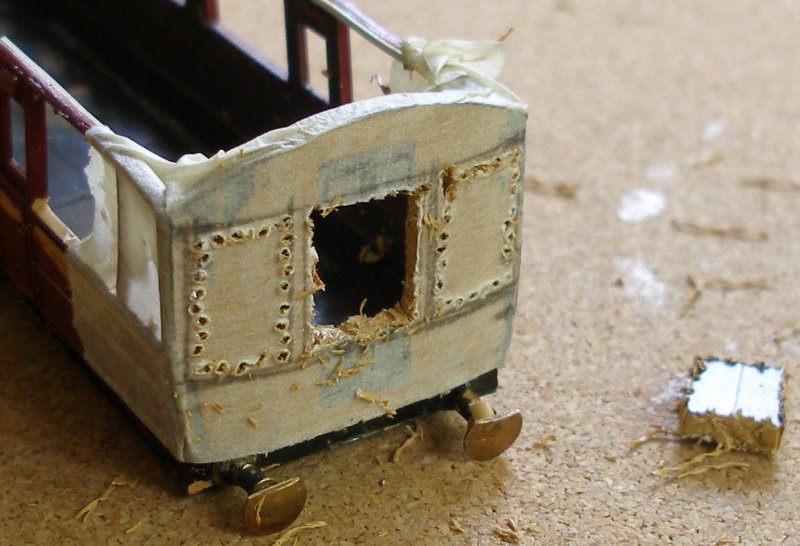
If you have got this far, you will see that this thread ceased in mid-2016. There was a very good reason for this, which was that at this stage in the build process it was obvious that the model was going to fail on two counts. Firstly, I could not achieve the neatness of cut required, and the ends were going to look rather crude and poorly-formed. It was also apparent that some of the areas which had been successfully cut out were very fragile and unlikely to survive any prolonged handling.
So the model has lain in a draw for the past for exactly six years, and was removed from the draw for reassessment on 8 August 2022!
What prompted this revival of interest? As will become apparent on other pages, a major game changer for me and my modelling was attending the Missenden Modeller's 3D printing course 4-6 March 2022. This is run by Justin Nevitt and is something of an intensive two and half days, which ends with your head spinning. However, the enormous potential of 3D printing was apparent for railway modelling purposes.
In the intervening four months the machine has produced signal boxes, hen houses, permanent way huts, stack of rail chairs, a rail cleaning car in the Pendon style, a manual point changing mechanism and much more!
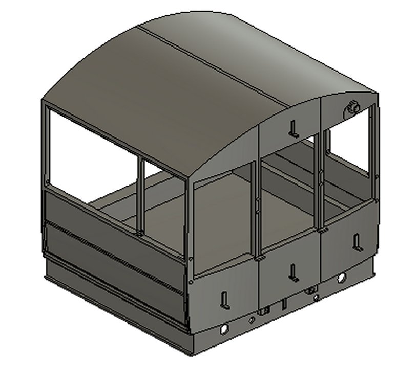
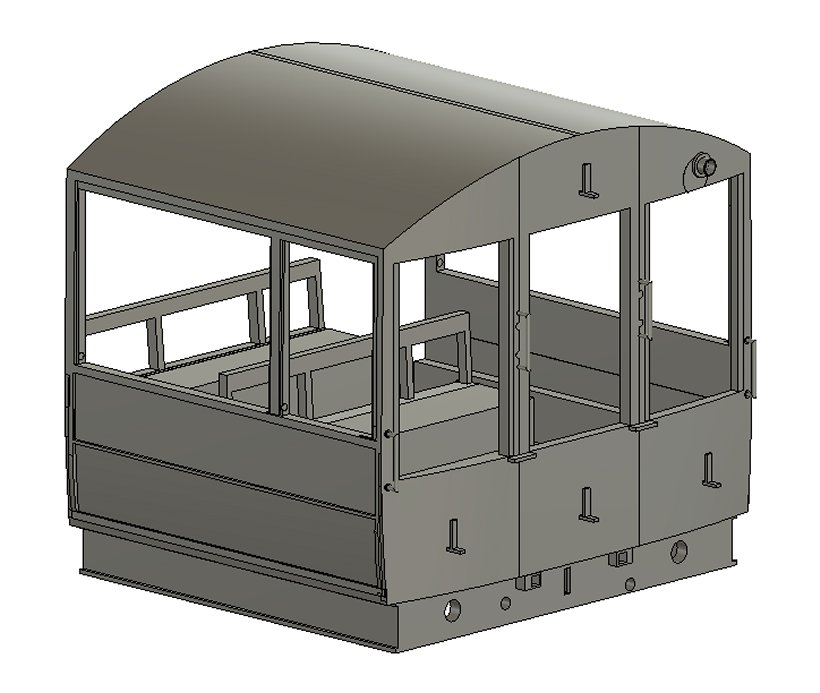
The Inspection Car was an obvious target for this process, so an afternoon was spent drawing up an end module in Fusion 360, as per the screen grab below.
Both ends of the car were similarly modified, presumably to facilitate being able to run both ways on the selected route without having to be turned. For this model the intention now is to cut the original ends off and glue the 3D printed alternatives in their place. There are three steps required to produce a 3D print; the design (as above), the 'slicing' of the model and the addition of the scaffolding, and then the actual printing. The screen grab below shows what the Chitubox slicing software has done to made the model ready for printing.
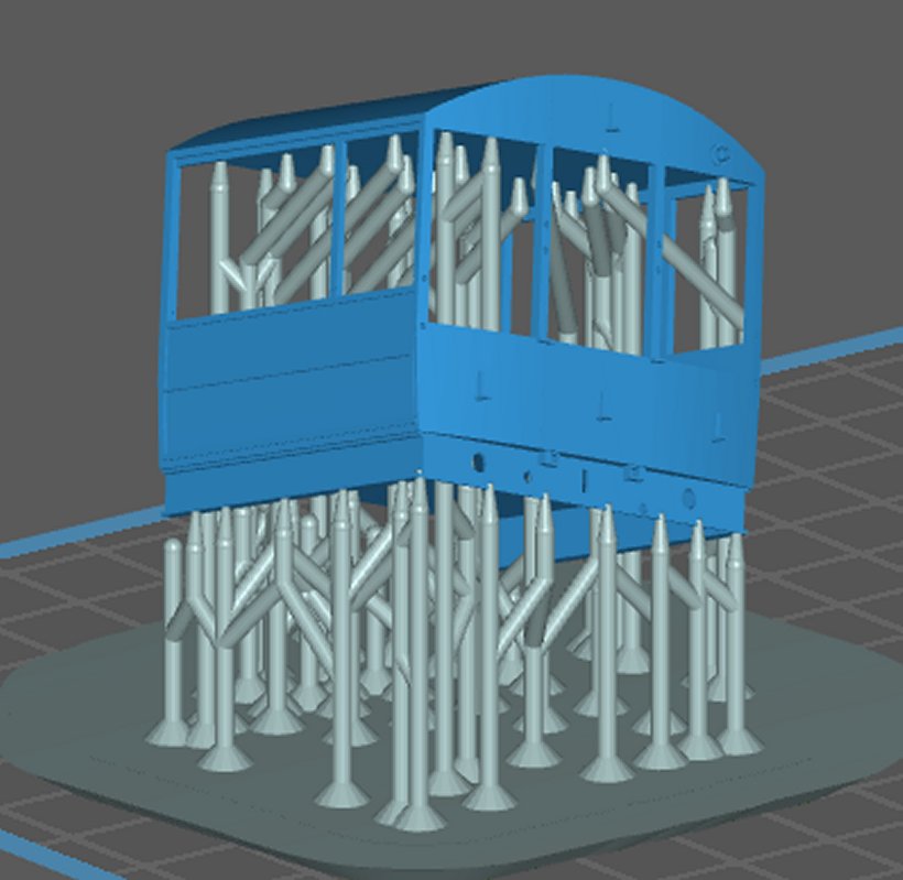
This may look daunting if you have not encountered this process before, but the software is both easy to use and does much of the hard work for you.
The key is orientating the model, so that it is tilted at a jaunty angle from the flat. The reason for this is that model is printed in layers, and the printer does not cope well with printing a large flat surface in one hit. So if the model is placed at a jaunty angle, the machine will only attempt to print a small part of the model at any one time.
The design was started at about 2pm, with a 2-hour break, and the sliced model ready to be loaded into the printer at 9 pm, so the design has taken about 5 hours.
It would have been possible to print both ends together, but with home 3D printing there is a high risk of failure for an untried, new design.
For people new to 3D printing these failures seem incomprehensible. The basic issue is that there is a printing plate that goes up and down into and out of a tray containing the grey liquid resin. The bottom of the tray consists of a plastic sheet, the FEP.
When the Ultra Violet lights at the bottom of the machine fire off they cause a layer of resin to set solid, and adhering to both the metal printing plate and the FEP sheet. Once the layer is cured, the metal plate starts to winch upwards and crucially the model has to adhere to the metal plate and not to the FEP. It is when the FEP wins that particular battle that the model fails. And you have to remember that the above model has some 1,125 layers, so there are 1,125 opportunities for failure.
Anyone interested in learning more should spend some time on YouTube which has some extremely useful videos dealing with the multitude of issues that arise on a daily basis.
I have set the printer going at 9pm, and the machine reckons it will take about three and half hours to print, so will be running over night.
And that's as far as we can go tonight :-)
This is the view that greeted me at 06.08 am this morning!
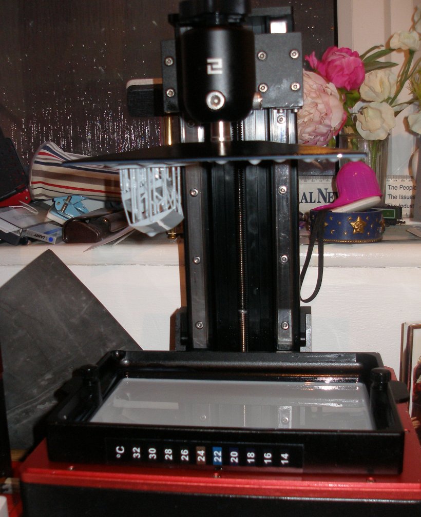
The model is the grey blob suspended from the plate at the top of the picture, in all of its unwashed and uncured glory. Note the self-adhesive thermometer stuck to the tray, which is showing a temperature of somewhere around 23 degree Centigrade. The minimum optimum temperature for resin printing is 22 degrees so this is a good number.
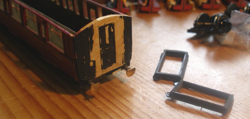
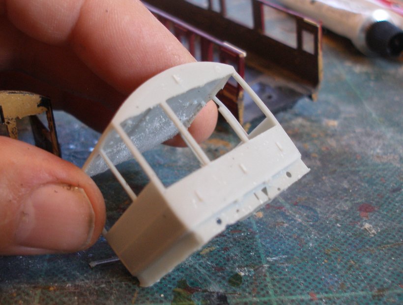
Now the new end can be compared to the original. It is apparent that the detail is much crisper on the 3D version. But you can also see where I inadvertently cut away one of the window pillars in error. Had the model been perfect in all other respects I might have had a go at repairing this with Microstrip.
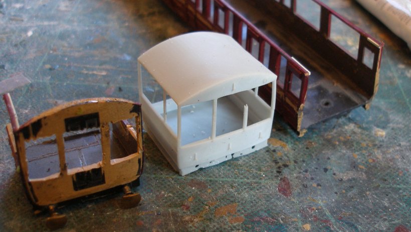
However, the model has a number of flaws in this Beta version. The buffer beam clearly wasn't thick enough an has partially disintegrated. I also concluded that all of the window pillars needed to be wider: not for modelling reasons but comparing them with the prototype photos. Likewise, the beams forming the underframe were too far apart and had to be moved in-board.I had created holes for the four small handrails that adorn the front of the coach but these have not printed.
And now to the redesign. I have decided to try and print the handrails: this is a gamble but worth a try. All the window pillars have now been enhanced. But the big, blindingly obvious detail to add have been the first two bench seats to the interior.
It is a three hour print job, so will be interesting to see how successful these changes are at mid-day :-)
The design featured a solid roof section, to give the 3D essential strength, and was to intended to fit inside the original roof moulding. In reality, this section was too large and needed reprofiling, and then it became apparent it wouldn't be possible to fit either the glazing or my Langley seated assorted loco crew! Two prints later, and it has been possible to trial fit the first of the two new ends.
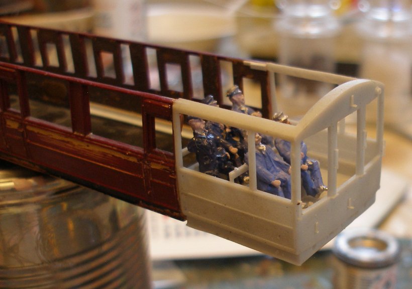
The Langley crew sit nicely within the model, although a couple of them had bought their shovels along, and so had to be persuaded, with a set of clippers, to leave them behind.
Another day, and a 3D print fail.
All I needed to do (!) was print a repeat second end overnight, and the job would be done.
However, I got a fail, and this is what it looked like.
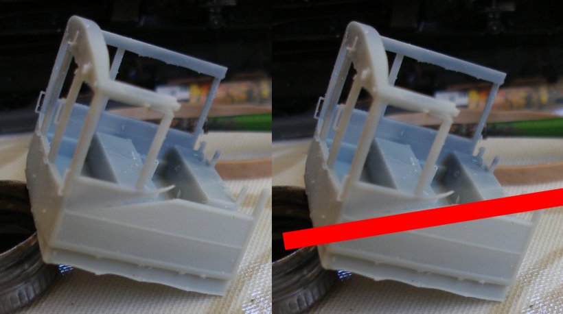
The left hand photo shows what the print looks like, and the right hand shot has a red line to mark the failed layer.
This is probably entirely of my own making. If you look carefully at the left hand photo you can see on the rear wall that the resin is of a darker grey colour; there is a pieball effective. This is because I realised just before going to bed that the tray did not have enough resin to complete the print. So I added resin that was in a bottle that was not pre-heated (I have a heated home brewing stand that the active bottles normally stand on to keep them at a happy 26 degrees C). If you look at the rear wall, the pieball effect is above the failed layer, and I suspect that the arrival of resin at a differing temperature has led to the failure.
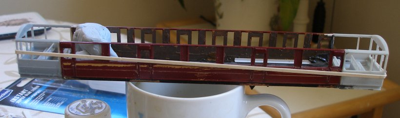
Best foot forward, and careful and full mixing of the resin, and here is the coach body with the two new ends now added, and waiting for the glue to go off :-) The BluTak is to keep the tops of the body sides aligned with the new end.
And now the final scamper to complete the model and get it onto the layout :-)
The day was obviously going to be another scorcher and excellent for spraying. With the filler applied the previous evening and filed down, both side and ends of the coach were coated with Halfords Primer. I used white because I had just run out of the preferred grey.
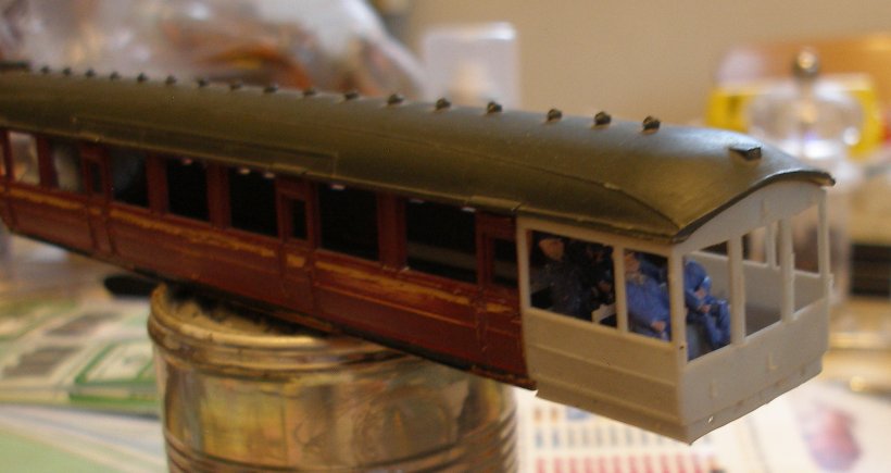
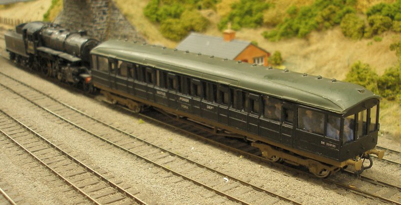
Things now started to role. The terraced flooring and benches were added, and the body sprayed with Halfords Matt Black. The bogies were then added, and it was ready for the next photo shoot.
The available photographs suggest that the centre section retained its partitions and seating, so the original Ian Kirk fittings were put back in. There is also a glass pane on the compartment side that is white, and was achieved with white masking tape applied to the inside of the glazing, which was also added.
Some temporary trussing for the underframe was cut down from an old Kitmaster kit, and the Langley seated drivers finally added.
And this is the photo showing the completed car in action, with the photo that started it all for comparison. The two obvious things now outstanding are a bolt and nut to secure the roof to the body, and probably at some point transfers for the sides declaring ownership by York Motive Power Depot.
And if you have reached this point, and are considering a similar conversion, drop me a line at the email ID below and will quote you for supplying a pair of 3D printed ends.
One more push! I needed to produce some transfers for another project, so thought a set for the Route Learning Car were needed to finish the job.
13 August 2022
Copyright J K Wallace, t/a 'Hall Royd Junction' 2013-2023 email: Hall Royd Junction
7 Portobello Close, Chesham, Bucks. HP5 2PL, UK
tel: +44 (0)7513 412880