
Model railway point control - case studies that work
PECO motor base plates : Side mountedPL-11s : Under baseboard manual rods : DPDT slider switches
From regular correspondence with fellow modellers the laying and operation points is a of re-occuring theme.
Both the operation of the points (how to change them remotely) and what to do with the frogs are permanent major issues.
Now its possible that people find the elaborate and colourful wiring diagrams frequently provided off-putting.
There is also something of the 'dark arts' about point installation. Some people seem to cheerfully wire up a shed load of points in an evening and have them all working perfectly - I write this having seen a photo in one of the Facebook groups where someone had wired up (but not installed) 77 point motors in an evening! Others struggle to set-up a single point.
My first efforts for the current build between the start in 2012 and now (2017) have seen a surprising number of failures, some of which are documented on this site.
So the aim of this page is rather than give blow-by-blow accounts, illustrate the four 'winning' strategies in the hope they will point the way towards your own winning solutions.
Summary
Here are the ways you can change your points:
Manually: blades moved manually; manual point lever; lever frame connected to points or other remote rodding
Electrically (solenoid): PECO, Seep, H&M, Gaugemaster
Electrically (motor driven): Tortoise, DCC Concepts, Fulgurex, Minx, servos
Memory wire has also been used, but seems to have lost favour.
My layout features a double junction as its centre piece, supported by storage yards 'off scene'.
In the scenic areas the points are hand-made using copper-paxolin sleepers. This means that the point blades are sprung and therefore have to be locked in some way each time the point is changed. Accordingly the classic PECO solenoid is not suitable for these points.
I had a lot of PECO motors, bases and points rescued from the pervious layout, and therefore these have been re-used 'behind the scenes' on the points that are located at extreme ends of the layout or behind the backscene where it would be difficult to access when operating the layout. The points they work are all PECO as I wanted ease of installation.
My perennial issue with both PECO - but more so with Seep - is that they have to be mounted under the board and it is difficult to ensure that blades were correctly whilst holding the motor in place underneath. My first ever motors were H&M, now no-longer available, although there is a clone. Although robust, the armature had an irritating habit of jamming and its internal polarity switch rarely worked.
I even had issues with the much rated Tortoise! I found some of my points were too stiff and the operating wire deflected without the points being changed. DCC Concepts have something similar with apparently a thicker wire but I haven't used it.
The Fulgurex featured a motor on an open frame which wound the armature back and forth. By definition, this was self-locking, although the frog polarity switching could be erratic.
The Minx was a brave attempt to provide a small and compact low-profile activator (motor) that could sit next to the point. I bought six of these, and the motors were excellent, but let down by an over-sophisticated control module that required constant re-setting.
I have used the PECO point motor system for a very long time, yet what looks like a simple system can be difficult to set-up.
In the original system the point motor could be clipped to the bottom of the point beneath the tie-bar, and a hole cut in the baseboard for the motor to sit in.
PECO are abandoning this particular option, as and when points come up for re-tooling. This omission can be seen on the new OO Bullhead point. The idea is that motors can only be mounted below the baseboard, and will engage with one of three holes in the tie-bar. Now I have always found this very difficult to reliably set-up.
Consequently I prefer 'above board' installations as it is easier to install and then subsequently tweek.
I tend to use the base plate for points behind the backscene using the PL-10, and the PL-11 side mounted solenoid motor for locations where there is baseboard framing preventing an underboard solution.
Incidentally the low-current coil (green) PL-10W is rated at 1.2 Amps, whereas a number of DCC Accessory Decoders are rated at 1 Amp.
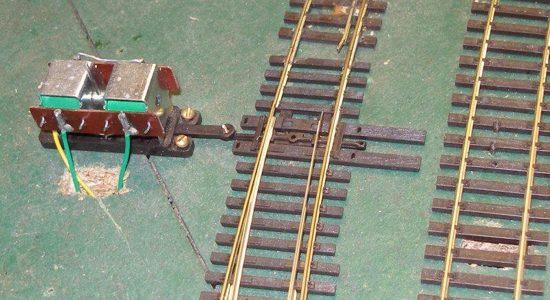
In the photo below there is a base plate and motor installed on the layout. The motor has to be fitted to the plate, and then placed next to the point with the hole at the end of the actuating arm placed over the spiggot on the tie-bar. The whole assembly should be at right angles to the track. The solenoid then needs to be worked by hand backwards and forwards whilst the base plate is held firmly. When you are sure the blades snap easily into place in both directions, drill a couple of holes and insert the screws through two of the holes. Once they are in place, you can then drill and fit the third screw in a more leisurely fashion.
If there is a criticism of the design, it is that once fitted, there is no movement allowed by the screw holes to adjust the throw. For instance, if the base was bigger so allowing the holes to be elongated, it would be possibly to loosen the screws and move the base backwards and forwards to optimise the throw.
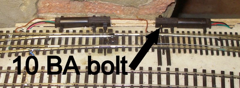
This photo illustrates the issue with the new tie-bars that PECO are introducing. These no-longer have the familiar spiggot at the end of the tie-bar, and to attach the rod you need to insert a 10BA bolt through the hole in the tie-bar, as shown in the picture below of the PECO US Code 83 curved point (if using these, the frog flangeway needs to be deepened).
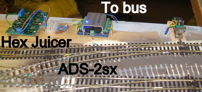
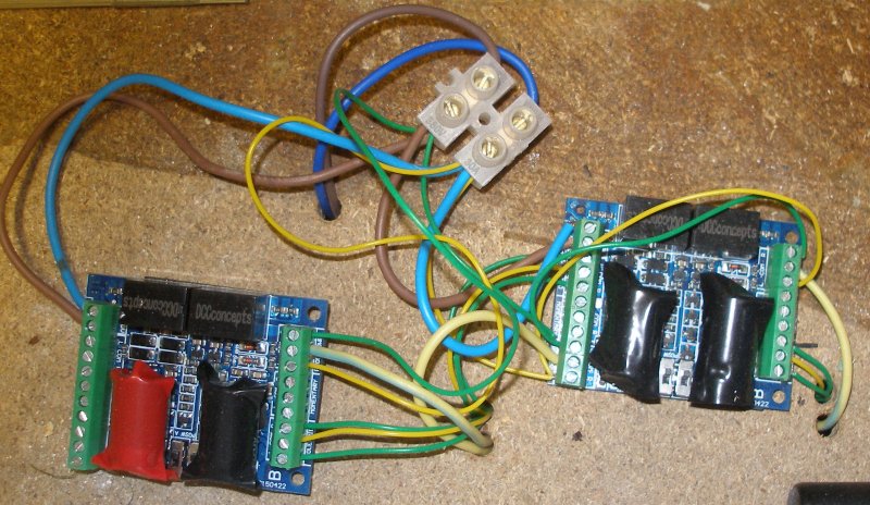
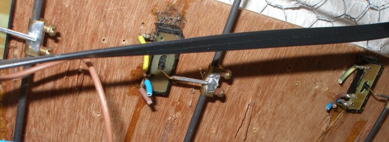
The second image shows some of the electronic gizmos that can make life easier. On the right is the PL-10W sitting on its base. I had bought a number of different decoders and systems, and found that to make these work I needed a number of alternative power systems, so as well as the traction bus powered by the NCE Powercab, there was a 12 volt DC power supply in parallel with a 16 volt AC system to power the various accessories.
Now all the PECO solenoids are powered by the DCC Concepts ADS-2SX, as seen in the centre rear of the photo. It contains a Capacitor Discharge Unit (CDU). This charged up from the traction bus, so does not need a separate dedicated power supply. A handy purple light on top of the case indicates whether the CDUs are charged. This is a 2-way unit, and powers two points. The unit can carry out a number of functions, but in this scenario it is only switching the frog polarity in addition to throwing the point. Programming is straightforward. The programming slider switch is put into the programming mode, and the accessory selected using the NCE Powercab. There is nothing to indicate that programming has occurred! The slider switch is returned to the 'run' mode, and you should now be able to select and change the point.
The Hex Juicer supports other items in the vicinity. Again, the two wires from the bus (blue and brown) power the unit. The blue block on the left hand side has six terminals, and the wire from the frog is terminated in one of these. Henceforth when a wheel crosses the insulation gap onto the frog, the resulting short is detected and the polarity changed.
However it is not always possible to place the point base next to the track, and it is possible to place it some distance away from the point being worked, it this case of the other side of an adjacent track. The control wire is a piece of Gibson 0.9 mm brass wire. It is bent up at both ends, with one end inserted into the centre hole in the tie-bar. The underlay is cut away to create a channel for the rod to slide backwards and forwards under the adjacent track. Finally a hole is drilled in the operating arm on the motor base behind the original hole and the 0.9mm fitted into it. The base is then screwed down as normal.
PECO introduced a side mounted motor some years ago. It looks smaller and less robust than its bigger PL-10 stable mate. A couple were bought for assessment and never used. However, a tight location at the edge of the baseboard over the baseboard framing has seen them deployed.
The hole at the end of the arm hooks over the spigot on the tie-bar, and the unit gently pinned down as shown using PECO track nails. Three wires from the motor are wired directly to the DCC Concepts ADS-2sx (in this case the earlier version), whilst the wire from the frog is secured to the middle terminal in the area marked 'Frog switching'. The other two terminals are connected to the bus.
As before, the blue and brown wires are from the bus to power the unit, and allow the CDU to be charged. I have four of these units working PECO points, and so far, they have proved to be both easy to install and very reliable in operation.
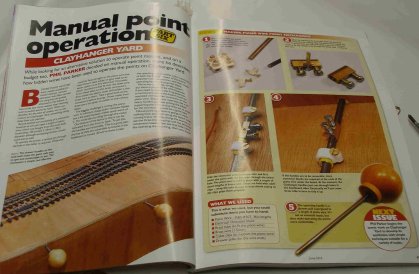
In the scenic area the points are clustered in two areas. The actual 'junction' the layout is based on are all on one 4 foot baseboard, and it was therefore possible to manually operate the points. I am very grateful to Hornby Magazine which had an article describing the use of piano wire under the base board and worked by a knob mounted on the fascia.

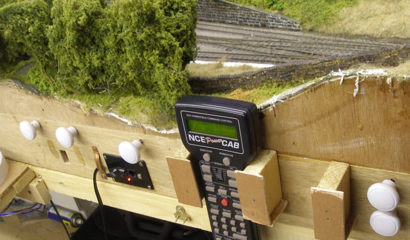
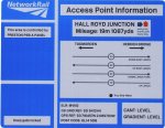
The photo below shows the Wilkinsons cupboard knobs along the fascia. The plate is a piece of Railwayana which neatly pinpoints the location of the layout.
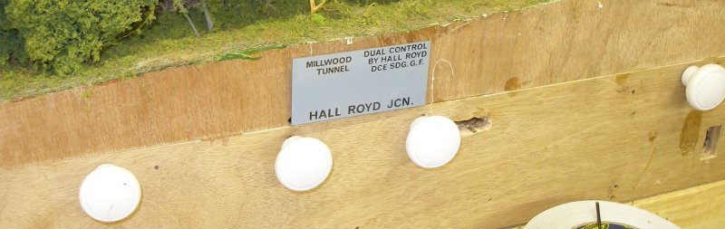
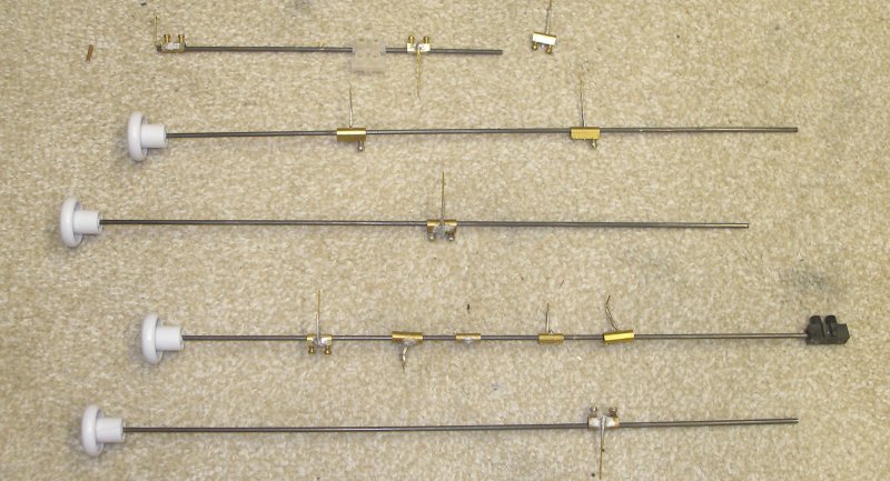
The points are changed by pulling or pushing the knob. The second photo shows some of the rods I made earlier for a section of the layout that has now been dismantled.
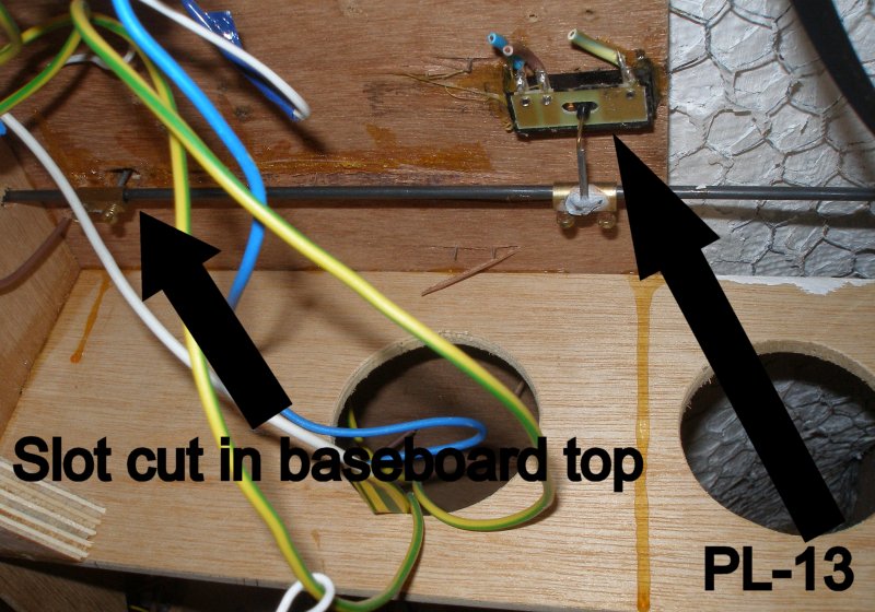
The Wilkinson knob glues neatly onto the end of the piano wire, and then a hole drilled in both the fascia and then in any baseboard framing directly in line with the first hole. This assumes there is already a hole in the point tie-bar, and that it is then possible to cut a slot in the baseboard top to take the actuator rod. In the original scheme the rod had to move both the tie-bar and the PECO PL-13 gluded under the baseboard to switch the frog polarity. To do this switching I opened-up a block of electrical terminal blocks and removed the piece of brass with the two screws sticking out of it. The actuator rods were then soldered to the blocks, and the blocks fed onto the rod after it was pushed through the hole in the fascia but before it was pushed through the second hole drilled through the framing. During this process the the tie-bar and SL-13 also have to be engaged. In fairness, this is the most fiddly part, but once done, it is a very reliable system.
This photo shows the 'control centre', with the double junction behind.
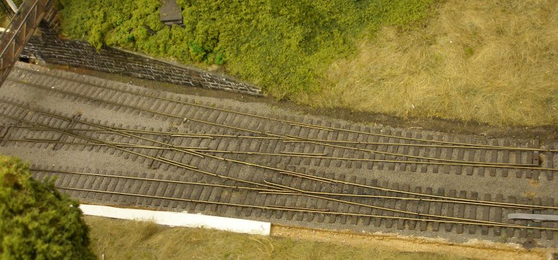
And this is the principle pointwork at this location. There is a double junction, and the diamond is enhanced, in that it is a single slip. Beyond the footbridge to the left is a cross-over, a trailing connection from the goods loop and two trap points, all of which are worked by the manual rods.
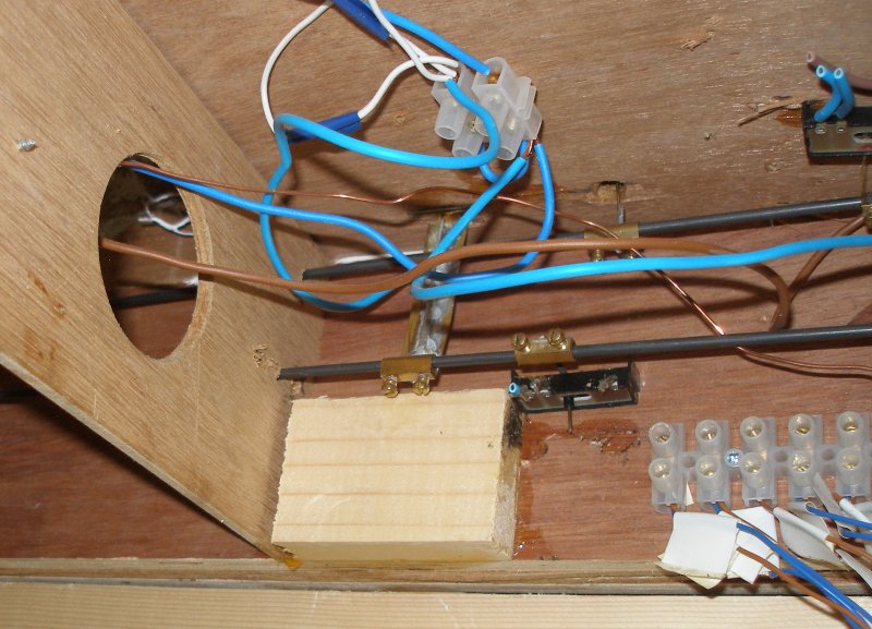
I always find shots under the baseboard rather disorientating, but in this shot you can see the rod with its two actuator blocks and rods screwed firmly to the rod. You may be wondering why the PL-13 has had its wires cut short...
This shows the rodding for the pair of 'king' points, with one rod directly above the second. Note how the actuator rod on the left is re-enforced to limit distortion when the point is switched. And again, note those PL-13 with their truncated wiring.
And for the avoidance of doubt, this photo shows how the PL-13s were glued to the underside of the baseboard before the actuator rods were fitted.
This proved to be a very cost-effective and reliable. An unexpected benefit was the speed with which routes can be set: a virtual frenzy of knob pulling and pushing!
The PECO PL-13s I have used for a very long tome, and I have found them very reliable. However, more recently they seem to have much more prone to failure, and getting back under the boards to re-affix detached lids was no joke.
Over time I have been installing Tam Valley Dept Hex Juicers (Gaugemaster make something similar). These are very simple to install. Basically the wire from the frog is attached to one of the six ports provided on the longer terminal block, and two wires from the traction bus attached at the other end. It's a delight. It works every time, and will also 'switch' a reverse loop or two ( so either six points or three reverse loops, or combinations thereof). At this point the PL-13s were rendered redundant, but it wasn't worth the effort of removing them, as the additional friction just helps hold the point blades in position.
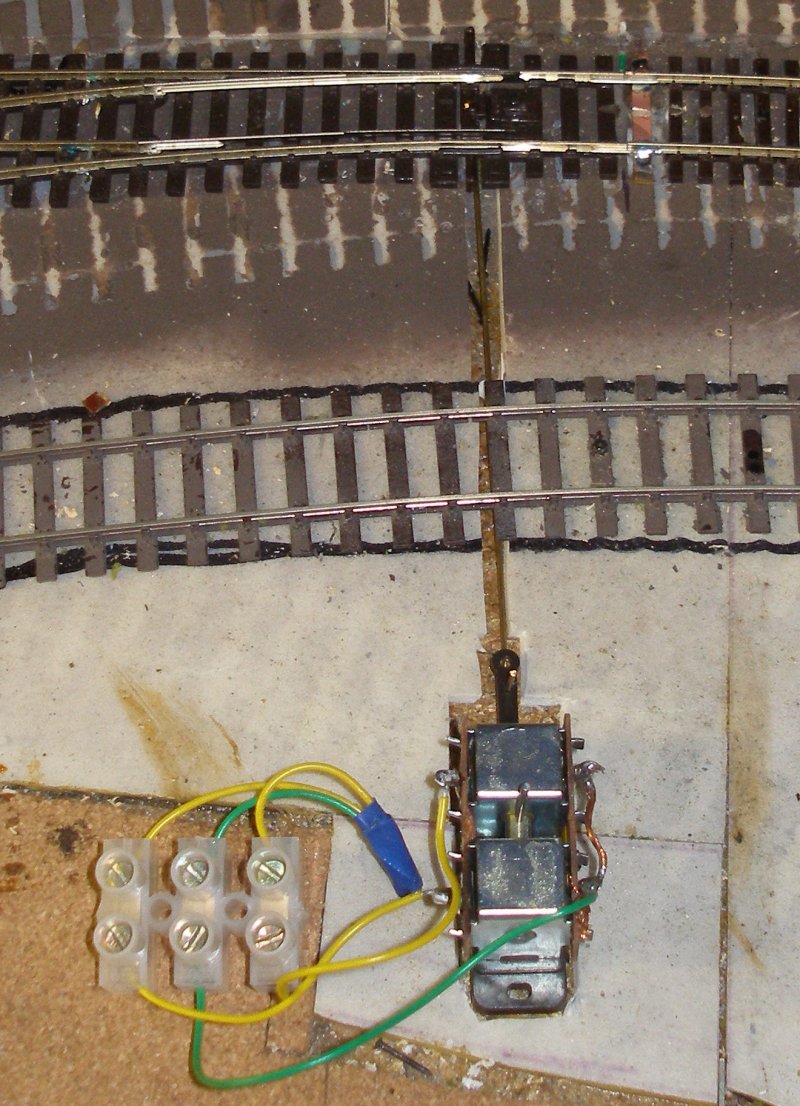
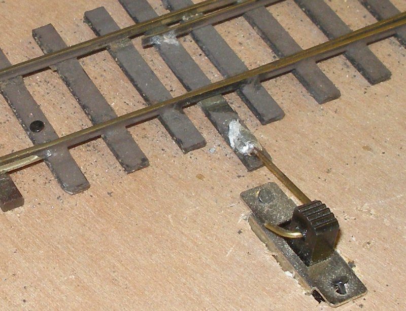
The storage yard runs down the other side of the loft, and as points at one end were adjacent to the main operator position, a simple manual switching system was needed. I have used Double Pole Double Throw (DPDT) slider switches before, and these are simple to install. A hole is drilled through the handle, and a piece of .9 mm wire inserted as shown. In this case, it is soldered to the tie-bar. Only one set of contacts are used, with the centre one wired to the frog and the other two to the track bus. You do need to get these two the right way round!
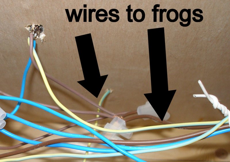
And the switch from underneath. The hole for the switch looks rather crude from this angle. The blue and brown wires go the traction bus, while the yellow wires are connected to the frog. The photo shows another yellow wire passing through the board to the frog located directly above.
Finally, a word on dead v live frogs debate (in PECO speak electrofrog v. insulafrog).
In summary, the dead (unpowered) frog is easy to lay in that it doesn't need any supporting wiring or switching, so 'lay and forget'.
However, the arrival of DCC has meant that the locos have to be electrically in contact with the track at all times - any one with a sound equipped loco will know how irritating it is when the sound cuts out when the loco losses contact for a nano second or two! This is also critical with the 0-4-0 steam and diesel locos, as it is possible to have a situation where the dead frog is actually longer that the loco wheelbase. Obviously, in this situation the loco will stall on the point.
So a combination of factors can force the adoption of live frogs.
Copyright J K Wallace, t/a 'Hall Royd Junction' 2013-2023 email: Hall Royd Junction
7 Portobello Close, Chesham, Bucks. HP5 2PL, UK
tel: +44 (0)7513 412880