
Stansfield Hall (Todmorden)...a representation
At Todmorden on the Calder Valley main line there is a triangle. At the eastern end there is Hall Royd Junction - the primary subject of the model.
Facing westwards on the model, the tracks to Copy Pit disappear through a hole cut in the backscene before joining the tracks that connect the various storage yards (or staging) that are located behind the back scene and on the other side of the loft. So there is technically a junction broadly in the right place, but, due to the configuration of the loft, facing the wrong way. To provide a connection to the goods loop that runs from Todmorden East to Hall Royd, and consequently there is a third track that passes through the hole in the backscene that does not have a prototype equivalent.
There was a need to conceal the backscene hole, and there is a handy uniquely-styled footbridge at Stansfield Hall with a handy accompanying row of eight terraced houses which would neatly fit in front of the backscene.
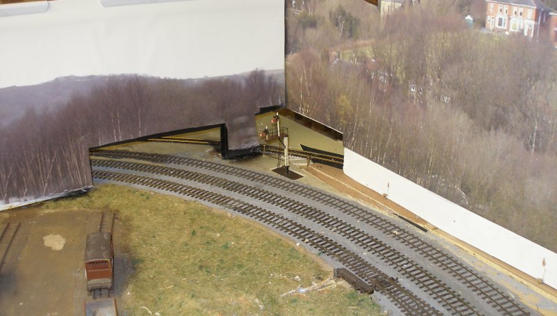
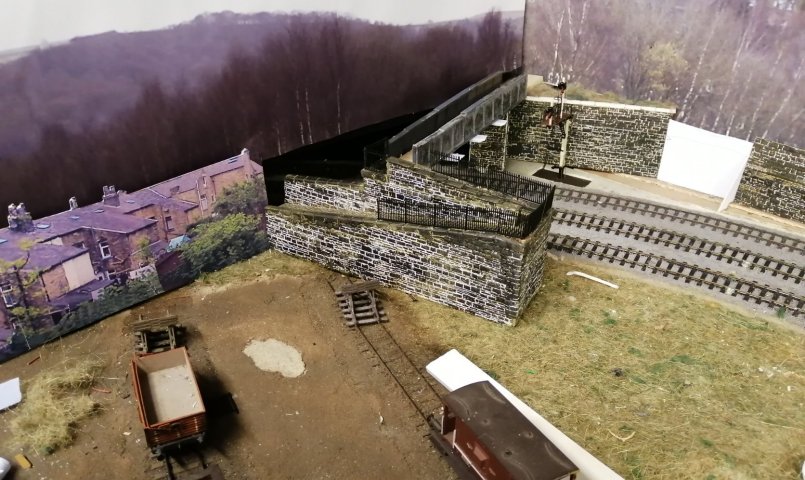
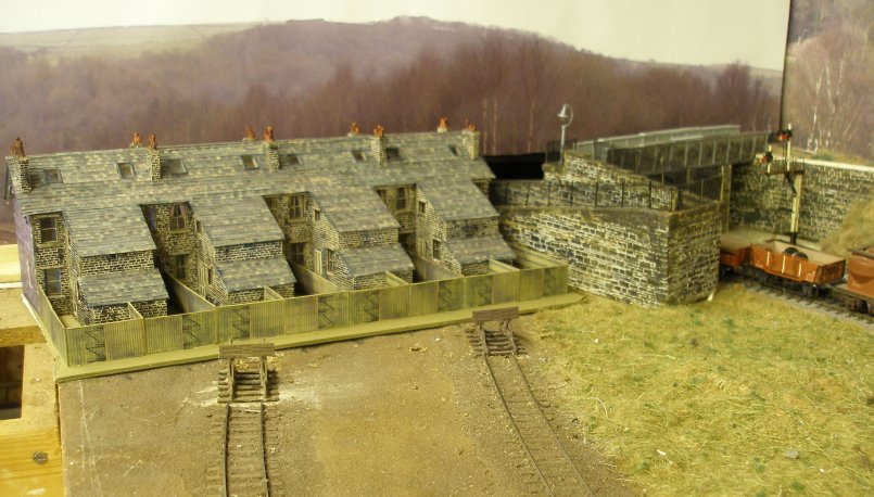
The first photo shows how the tracks leave the layout. On the left are the two engineering sidings. The inner track on the Copy Pit line actually loops back behind the backscene and returns as the Down Loop that runs from Todmorden East to Hall Royd, whilst the other two tracks notionally head to Copy Pit. Through the cut outs can be seen a single track which heads to the staging that represents Manchester Victoria and points west.
The bracket signal is effectively reversed: it is in the right place but controlled trains approaching in the opposite direction. In its current location it 'detects' the points controlling access to either the storage yard or the main down line returning to Hall Royd and Leeds/Bradford.
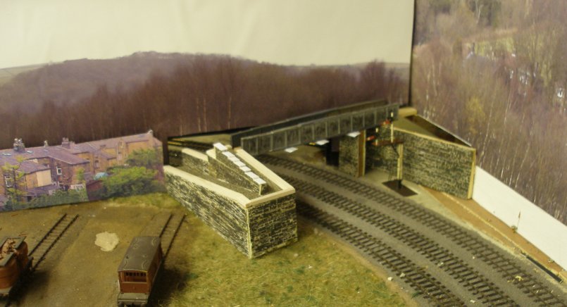
Rapid progress was made creating the basic structure of the western abutment. The girders are Wills varigirders, and came from the scrap box. Notice how a retaining wall has been fitted to conceal the Manchester track. At this stage it was planned to model the rear of Claremont Terrace in low-relief. A series of frames were pieced together from a video shot from the first train on the relaid chord to create the terrace. The abutments are mounting board (thick card) faced with Wills random stone sheets. These have been recycled from scenic features from a previous layout.
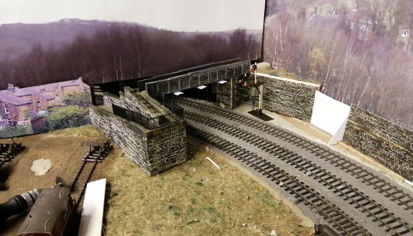
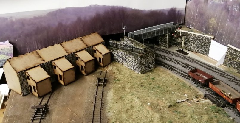
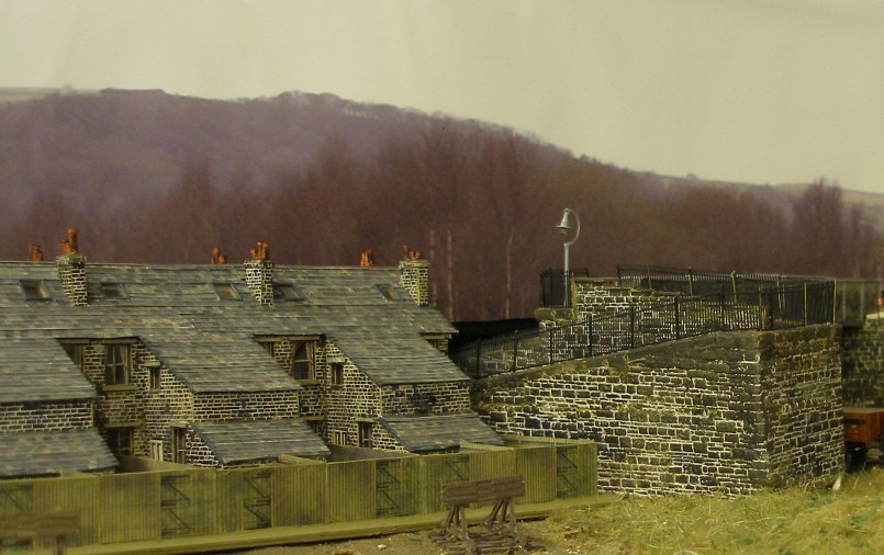
The next three shots show progress at day 10. The iron railings are GWR Ratio platform fencing, and the incline of the approaches is therefore set by the platform ramp fencing. The retaining wall along the right hand side has been further extended. In real life this is an earth bank, but there is insufficient room in the model.
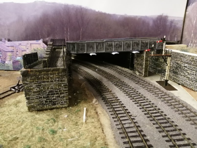
The smoke deflectors mounted on the underside of the bridge were initially a challenge. However a visit to the local Wickes and a length of the small size electrical trunking was acquired: the lid was a perfect match, as shown. For people who know the real bridge, there is now no evidence of the intermediate stone pillar (directly behind the left hand signal arm). This was demolished when the bridge was re-decked sometime in the late 60s or early 70s.
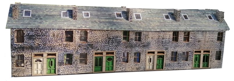
The low-relief Claremont Place predictably lacked depth, and so the search was on for a more full-bodied solution. The location is at the far extremity of the layout, and therefore some fudging could be allowed. The configuration of the rear extension is unique to this terrace in Todmorden, and is a rarity in model kit land. An intensive search of the Web found one house kit with this configuration. The 4 Track Models kit had the right footprint, but comes with a brick finish. It is also smaller than 'scale' in that the length and depth are compressed. The good news is that these reduced dimensions meant that the full terrace could be represented. However, it would appear that 4 Track Models have ceased trading, and the four kits required were acquired at a greatly reduced price. The Recommended Retail Price was £29, reduced to £10. At £116 this would have been an expensive solution, whereas £40 seemed a fair price given the amount of modification required.
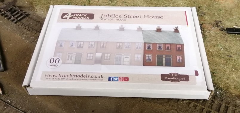
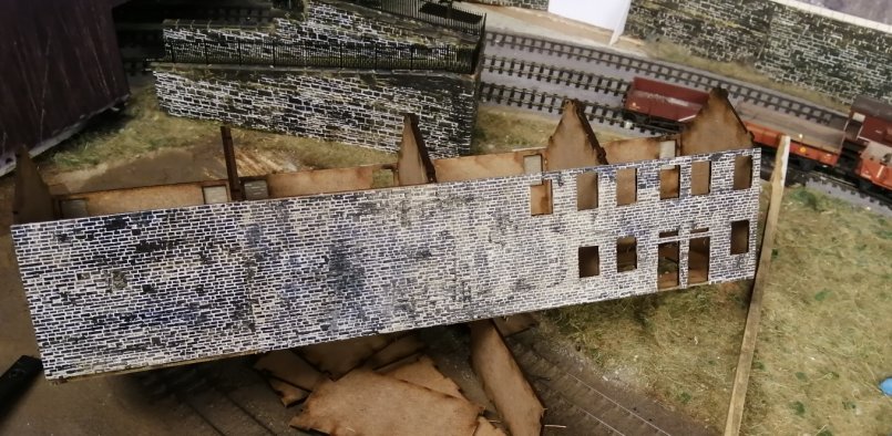
The kit is formed from laser cut MDF sheets. In many respects it is a nice kit, but there are some deficiencies which will be highlighted in the narrative. The box structure was assembled very quickly, and the full terrace created within an hour.
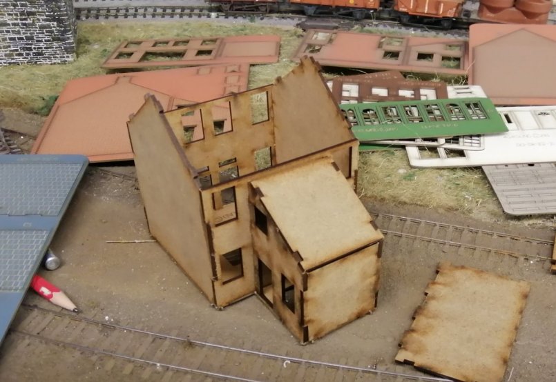
The terrace was trial-fitted in place. The alternative stone finish to replace the brick panels supplied in the kit has been glued to the rear elevation. The iron railings have now been fitted to the footbridge abutment, and the distinctive street lamp has appeared. The extent that the engineering sidings will have to be cut back is still undecided. Technically there should be both gardens, and a patch along the rear boundary providing access for residents.
The stone plasticard was pre-painted using Geoff Taylor's methodology as described in the 'Model Railway Journal'. This was glued to the sides using contact adhesive. The windows and doors were then cut out. Without giving it much thought, the 4 Track Models layout was followed, with two upper storey windows along the front of the house.
More attention was given to the rear of the terrace as this is the one facing into the layout. Claremont Place has a rear single storey extension, and this was formed from mounting card. From te available photos, there do not appear to be any windows in the extension.
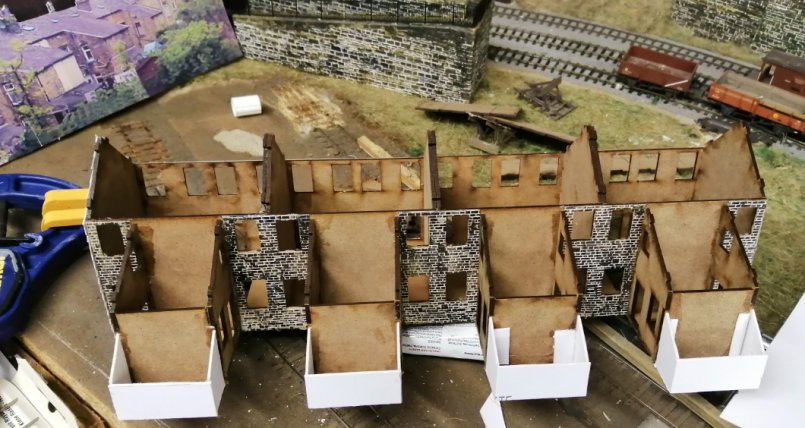
The stone cladding was added to the extensions, and a start made of slating the extensions. The roof stales are Howard Scenics which are now available from Freestone in Witney.
The windows were fitted as per the kit, complete with the curtains supplied. Claremont Place also features skylights front and back, and also has chimney stacks also ranged front and rear. Having initially completed the building, the front elevation didn't look right. The pair of windows on the upper storey made the front look oddly cluttered.
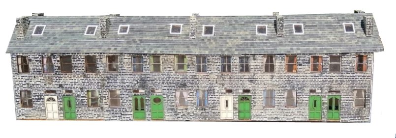
A quick check of the prototype suggested the extra windows needed to be removed. The plasticard was gently levered off and a fresh sheet cut and remounted on the front aspect. A further change was to cut out the door surrounds so that the stone edgings provided in the kit could be used. It should also be pointed out that in the original scheme, the building was going to be cut through on an angle so that it would have been truly low-relief and therefore the appearance of the front irrelevant.
This can be compared to this Google image 'grabbed' from Google Streetview. Of note, the stone edging to the front door matches the real thing. Some of the skylights on the front elevation have been upgraded in real life, but will be ignored as the front faces the backscene. Finally, the bay windows are distinctive, but are also being ignored as they represent an investment in modelling time that would have limited payback.
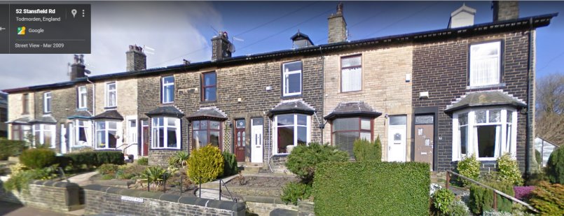
Source: Google Streetview
The other area being developed is the signal box. The model is a Peter Leyland original, based on Kirkby on the Liverpool Exchange - Wigan line. It is identical to Stansfield Hall in all respects bar two. Stansfield Hall has an extension on the right-hand elevation containing the lavatory, and the landing (at the top of the stairs) was extended backwards onto the bank at the back of the box.
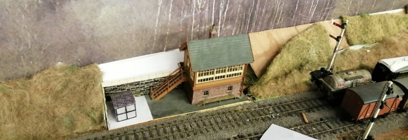
The area occupied by the lamp hut is where the brick-built coal store will go. Although not clear in the photos, there is a recess in the retaining wall which neatly accommodates the box.
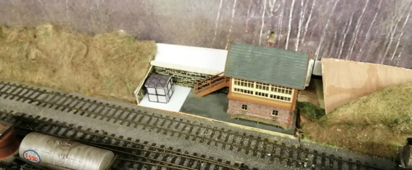
The old faithful Hornby Dublo Home and Distant signal is due to be replaced with an equivalent MSE item.
Clearly more to do...but these notes are being written on the hotest July day ever recorded so the layout is being left to stew :-)
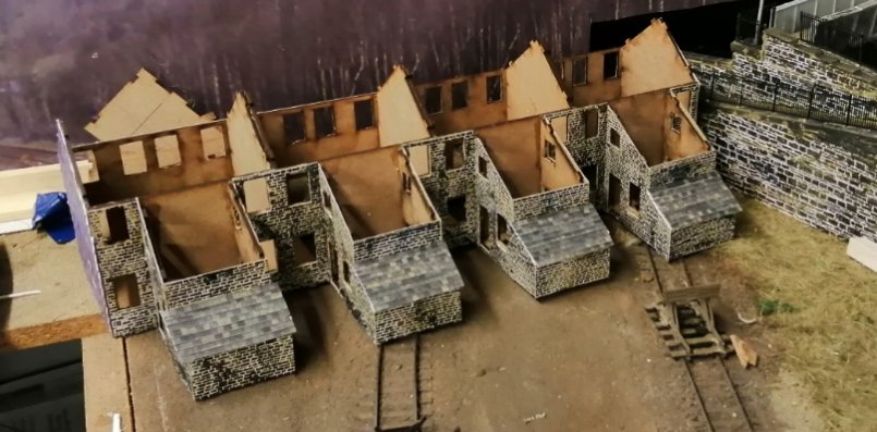
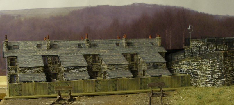
'Claremont Place' is now largely complete, with chimneys, backyards and fencing fitted (although the yards themselves still need detailing), and this is the moment that the terrace has been properly located on the layout.
A scale model it isn't, primarily due to its origins as a 4Track Models kit. The obvious flaws are:
1. the real terrace is stepped down the hillside, with the higher end to the right, and sloping down to the left..
2. the houses are actually below the railway, with the gardens sloping down towards the houses.
3. the footprint of the kit houses are small for the prototype, which should really be 30% longer and deeper.
4. the area to the rear of the houses are actually gardens rather than backyards, and the modern fencing is more of the chain-link variety, giving a more open appearance. However, the Howard Scenics wooden fencing (and slates) were surplus from two unbuilt kits.
5. on the prototype there are two additional houses at the right hand end of the terrace which fill the corner between the end of the terrace and the bridge approach ramp, but to fit the layout, the angles are wrong
However, the bits that are right are:
1. there is a path running along the back of the properties giving access to the gardens.
2. the left-hand gable has been clad in a slate that is more purple in hue than the roof slates and of a larger size.
3. also on the left-hand gable, the chimney stacks overhang the gable end, and are also clad in purple slate.
4. cut into the roof front and back are the skylights, and also a window on the ground floor in the left-hand gable.
5. chimney stacks have been added to the front and rear roofs (in the kit they were on ridge).
6. a rear, windowless extension has been added to each pair of properties.
The scene can only be viewed for trains travelling round the Todmorden chord towards Blackburn, and here is the composite view originally created to make a low-relief backscene.
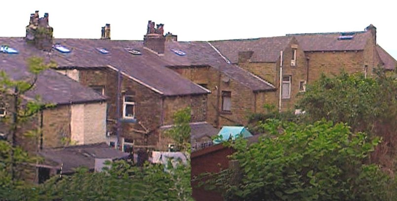
And here is the model...
8 August 2019

Copyright J K Wallace, t/a 'Hall Royd Junction' 2013-2023 email: Hall Royd Junction
7 Portobello Close, Chesham, Bucks. HP5 2PL, UK
tel: +44 (0)7513 412880