
Constructing a Craftsman L&YR Aspinall Class 27 0-6-0
For me, and I suspect others, Lockdown has triggered a major sort out of my model railway empire. The stuff in boxes in the workshop and under the layout has been pulled out and graded.
Some items just needed finishing or just plain fixing to give them a new lease of life on the layout. Some needed fixing but didn't have a future (wrong period, wrong location), so needed to be fixed and sold, and some were plain junk!!
I have always had a fondness for the Aspinall Class 27 0-6-0, but sadly Bachmann have yet to perform, tending to favour the railway that the LYR acquired in 1922(!). Some years ago I acquired a Craftsman kit of this loco, but each time I opened the box, I was put off by the mass of etched components, having not constructed a brass kit before.
In fact, I was so intimidated by the contents of the box that I bought a 3D printed body kit and a Bachmann Southern Class C at the start of Lockdown 3! The AJModels kit (available through Shapeways) makes up into a nice model. The only reservations I had were the brittleness of the 3D material, and possibly the lack of weight. Bachann incorporate a cast metal footplate in the original loco, which sadly can not be carried forward into the Class 27.
It was an original RMWeb blog that first described the use of the Bachmann Class C chassis under a Craftsman Class 27, as the original Craftsman chassis had disappointed. I mention this now, as there are aspects of the Craftsman chassis that are possibly questionable.
Three months into Lockdown and I had identified ALL the unbuilt kits in the house. These consisted of three Kitmaster and a single Coopercraft BR Mark 1 coach; six Airfix wagons and the Craftsman Class 27. Having just rechassied my Airfix 4F with a Comet one I had bought way back when, it seemed logical to roll into building the Class 27.
In the grand eBay sell-off that started in early January, I had used the proceeds to buy an Escap RG4 1616, and this looked about the right size if the motor was mounted vertically in the firebox. I then just need a set of wheels. I prefer Romford for their ease of quartering, and these come up pretty regularly on eBay. I didn't have any 20mm wheels in stock, and a set was soon acquired.
I sexed these into what I thought was the insulated and non-insulated, and then trial fitted them to the partially assembled chassis. I was somewhat nonplussed to find that just placing the 'raw' chassis on a live track, there was a short circuit. Removal of the wheels showed that I had insulated wheels that had been converted to non-insulated by inserting a piece of copper rod to bridge the insulation.
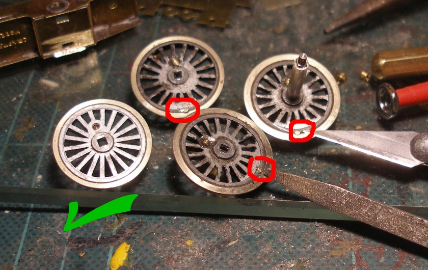
So of the six wheels supplied, only two were insulated. Given I was about to build an etched kit, it was only the work of minutes to drill out one of the rods, and so re-insulated the wheel.
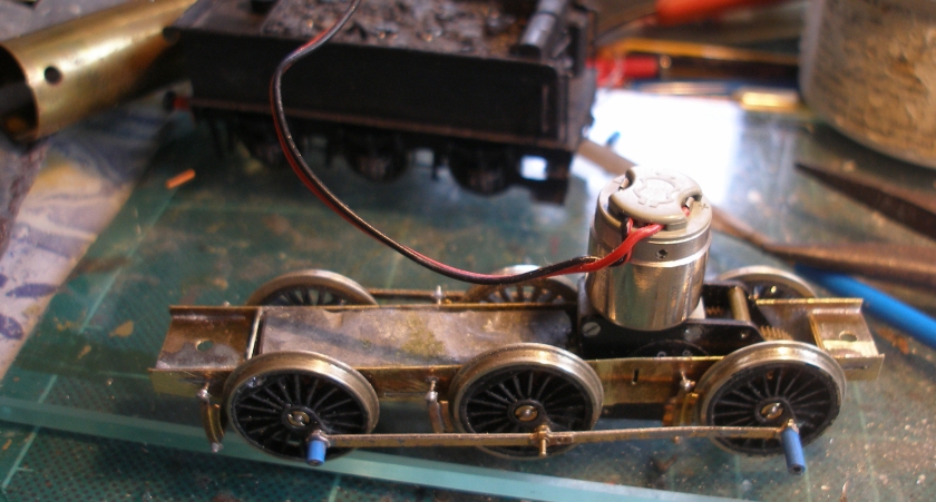
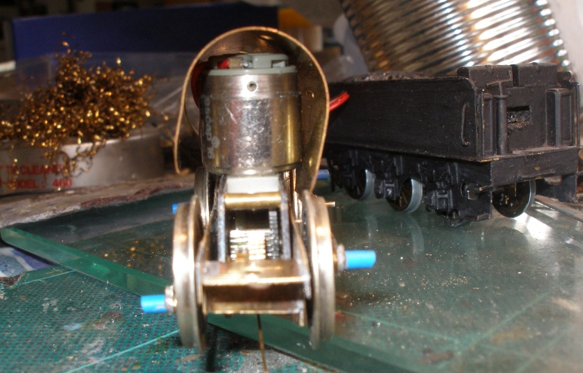
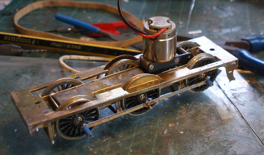
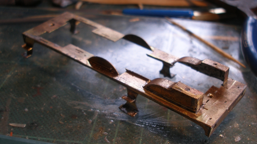
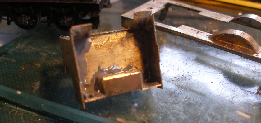
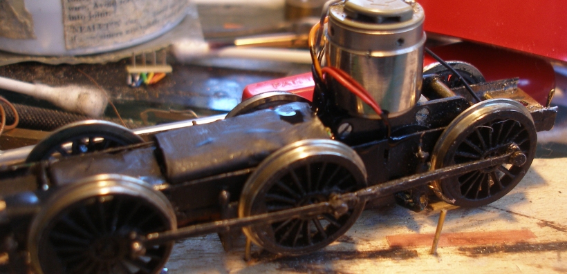
In this particular description, I am going to try and focus on the bits that people might have difficulty with. The chassis stretcher plate need a section cut out to accommodate the RG4. I felt that the material used for the frames was possible too thin, and something thicker/more rigid is required. Here is a snap of the completed chassis. I found running it on the test track that the front end had a tendency to bounce off the track, so I added some lead sheet between the frames. The chassis had obviously developed a twist, which was apparent when it was placed on a sheet of glass. This was corrected by twisting the chassis.
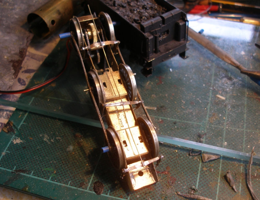
I use a circle of PECO fourth radius curves for testing, the thinking being that if a loco will comfortably negotiate fourth radius, it will be perfectly happy on my 3 foot minimum radius on the layout. I had deliberately left off the axle washers supplied by Craftsman, so that was plenty of play on the middle and front axles. It then seemed to me that the long, unjointed coupling rods where restricting the easy movement of the front axle, and I determined to see if I could find a pair of jointed rods.
 .
.
Now
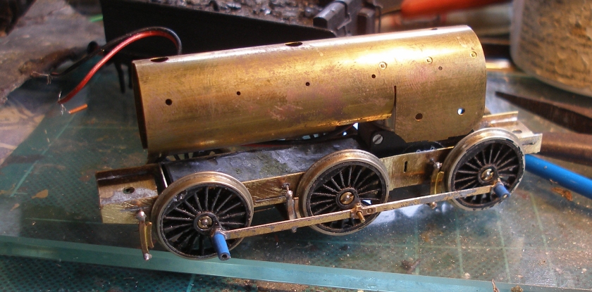
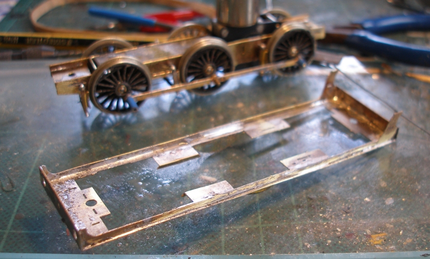
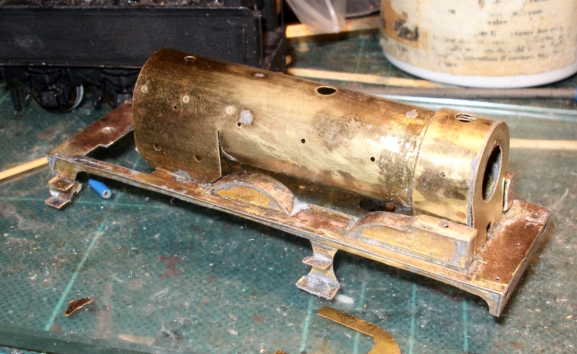
The next stage was to check that the RG4 would fit within the boiler/firebox, and the pre-formed boiler shell was placed over the motor.
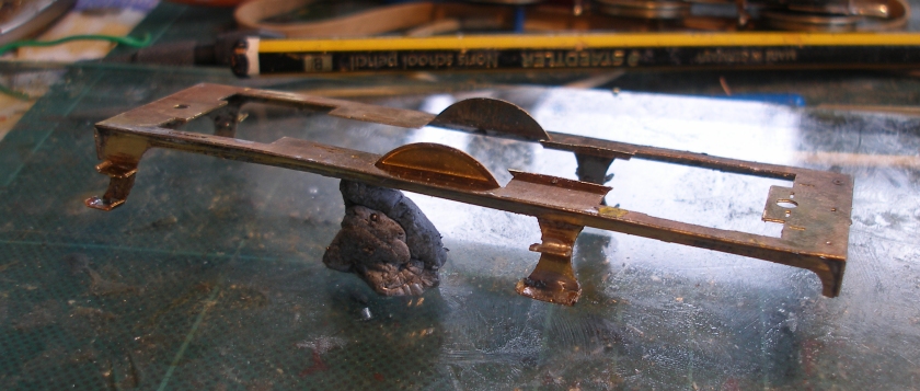
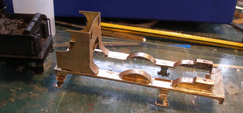
The footplate and valencing came good in he end! First I soldered the valnce the wrong way round, so cab end at the smokebox end. Then I didn't read the instruction, and soldered the firebox end flush with the rear of the footplate. I finally got it right with the valence equidistant from either end.
Next the steps were added. Note how all the soldering is being done on a piece of glass (possibly ex-bathroom cabinet) to ensure a totally flat surface.
The front splashers/sandboxes were then added. The sandbox tops are pre-formed, and fitted well.
Progress was surprisingly rapid, and now the cab is being trial fitted.
This was the point at which my trusty 18 watt Antex soldering iron was overwhelmed. I decided to continue, using J B Weld to glue the larger assemblies. My recent experience is that it seems to work better on metals than dear old Araldite.
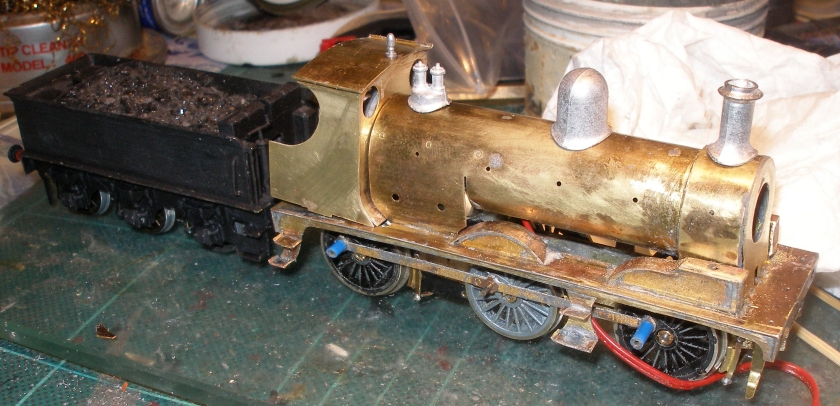
The three elements forming the smokebox were glued together, and then the boiler and smokebox were fitted to the footplate. I used the slots at the front to fit the tabs from the smokebox, but I have a suspicion that these might just be a tad too far back. The iron, however, was able to cope with soldering these elements together.
Progress was quickening, and now it was starting to look like a loco. If you were wondering how the tender came to be finished so quickly, it had appeared on eBay a couple of weeks earlier, and was a factor in deciding to build the loco.
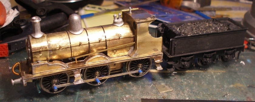
Another evening saw the loco substantially complete, and awaiting the paintshop. Two small issues. The hole in the front of the cab spectacle plate does not line up with the handrail. Secondly, there are no slots to fit the reversing lever into. In retrospect, I think the smokebox end of this should have been terminated over the back of the footplate framing, so further under the boiler. The handrail knobs along the boiler and firebox are medium, whilst I used short one on the smokebox, and on the smokebox door. A new development for me has been the use of insulation tape for the boiler bands. These were put on before the body was given a final scrub, and they have proved superisingly durable.
Now was the time to return to the jointed coupling rods. It had been suggested to try the Alan Gibson universal rods, and the following photos show the sequencing of their construction and fitting.
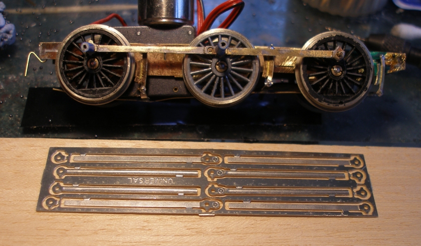
The first thing required was a jig. This is a piece of wood, with holes drilled into it using the original rods as a template. Three pieces of .9mm wire were then inserted into the holes and glued into place.
The half rods were carefully cut from the fret, and then the rod ends placed over the brass rod to judge how much need to cut from end rod. The original is laid out on the jig to get the orientation of the new rods right. These can be made fluted or plain, and the plain side was needed with oil caps above each crankpin hole pointing upwards (otherwise the oil would fall out on the real thing :-)).
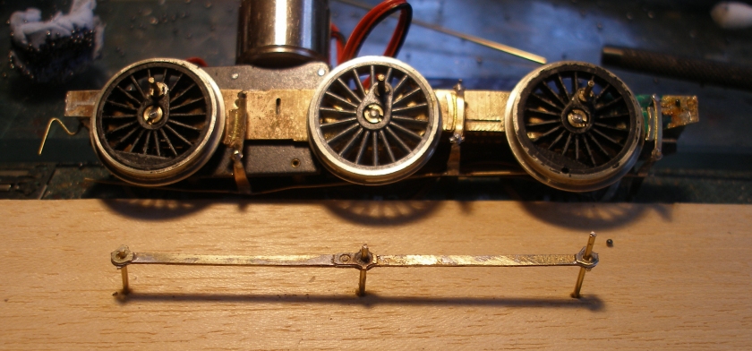
Note also on the fret are the rod ends, and these to be carefully cut off, tinned and then carefully placed on the single layered end of the rod to give it strength. Care is required here, as one burnt itself into the wood of the jig, and pinged into outer space when I tried to lever it off the surface with the scalpel. Another I tinned on the wrong side, so do check the orientation.
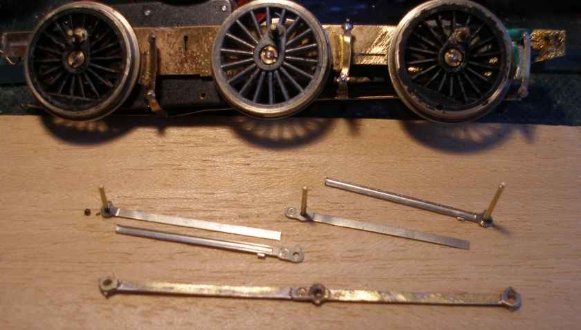
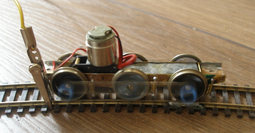
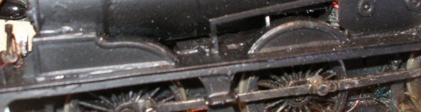
Although I drilled out each crankpin hole, I also eased them by inserting the sharp end of the scalpel into the hole, and gentle rotating the blade. This ensured that the rods were an 'easy' fit, rather than a tight fit. Remarkably, without any further tweaking required, this is the outcome on the test track.
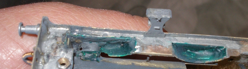
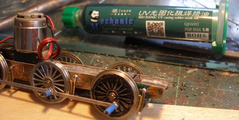
One other aspect of this build is worth sharing. With etched kits there is the problem of the wheels shorting on the underside of the body. 'Solder Mask' was suggested to me as a possible solution. This is a rather beautiful dark blue/green in colour. It is dried by exposure to Ultra Violet light, and rather handily, I had such a torch. I applied this to the underside of the splashers and to the frames behind the insulated drivers, having observed on the test track where the arching was occurring. As previously noted, I had deliberately left the washers off to allow the wheels to better curve on small radius track, and so this was a neat solution. It is available on eBay, but do order from someone who holds stock in the UK.
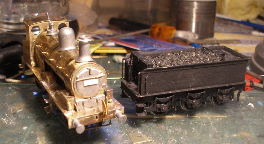
Remarkably two Craftsman Aspinall tenders came upon eBay within week of each other. The first had a solid floor, which I haven't yet worked out how to cut through it, as it was my plan to fit the decoder within the tender tank.
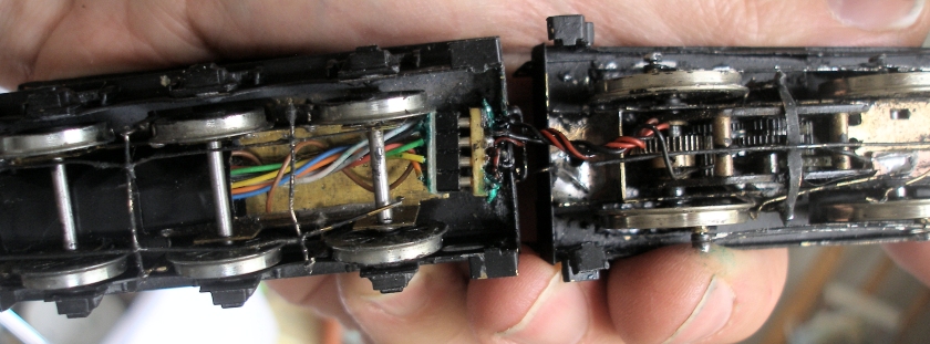
The second one I won uncontested, as it was listed as 'Cratsman Tinder with spout or funnel'. This was unpainted, did not have a solid floor to the tender tank (so possible to put the decoder inside the tender) and coal rails. The tender was washed down with a domestic product with a anti-limescale element, and then very quickly spray painted, and appears in the photo of the loco on the layout. I then found that the Zimo decoder slide neatly inside the inside tender frame, and this tehn allowed the DCC socket to also act as the loco/tender connector.
The decoder has had the wires folded back on top of it, and then wrapped with insulation tape to stop the wires hanging down and impinging on the axles. This 'assembly' has then been pushed from right to left inside the inner tender frame. The friction fit (with the tape) ensures that the decoder is in the 'roof' of the space, and so also clear of the wheels and axles. The green paint on the soldered tabls on the decoder socket are 'Solder Mask', which forms a very effectively insulation, and so avoids the need of insulation tape. The use of tape would have meant it would be difficult to unplug the decoder, and also would have meant that the socket would not have been such a neat fit.
 .
.
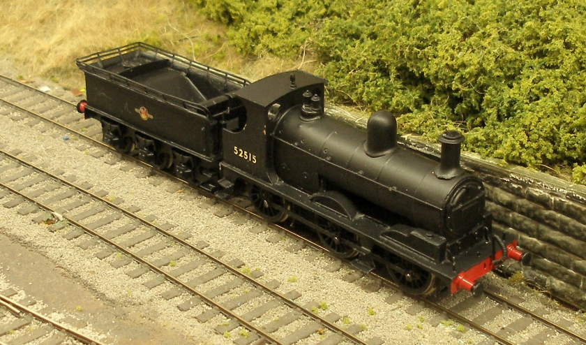
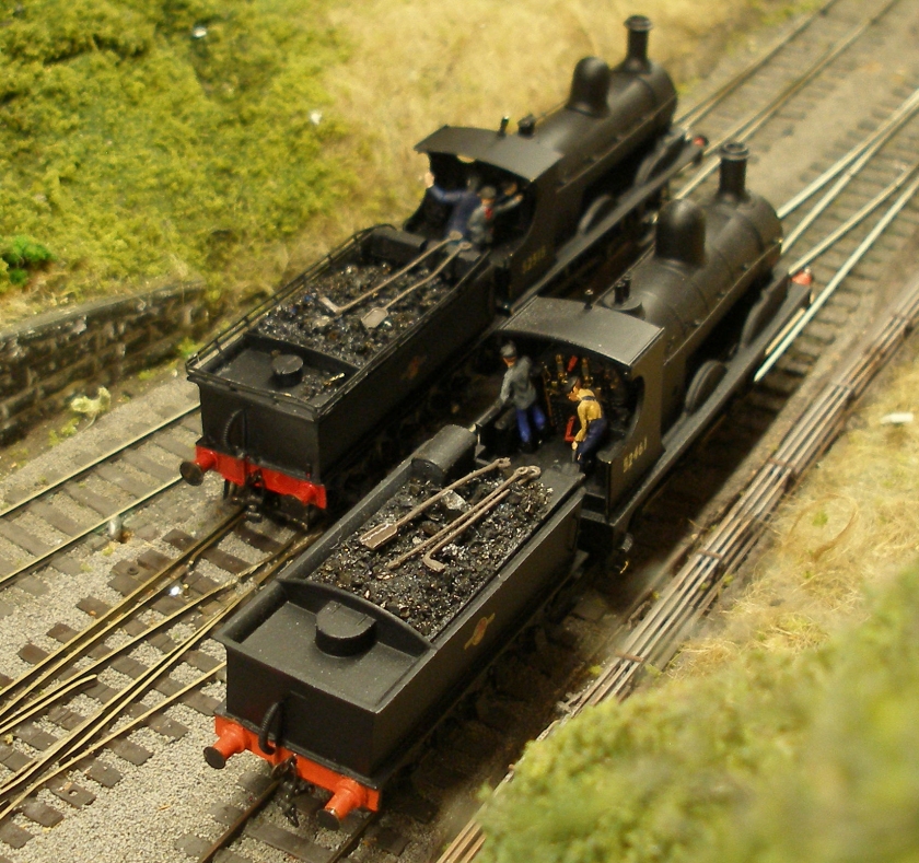
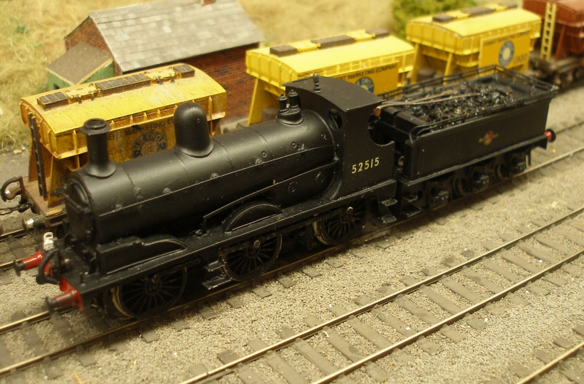
Still needing crew, coal, fire irons, lamps, couplings and smokebox number, here is its first appearance on the layout.
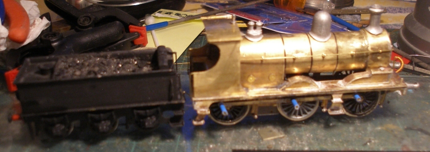
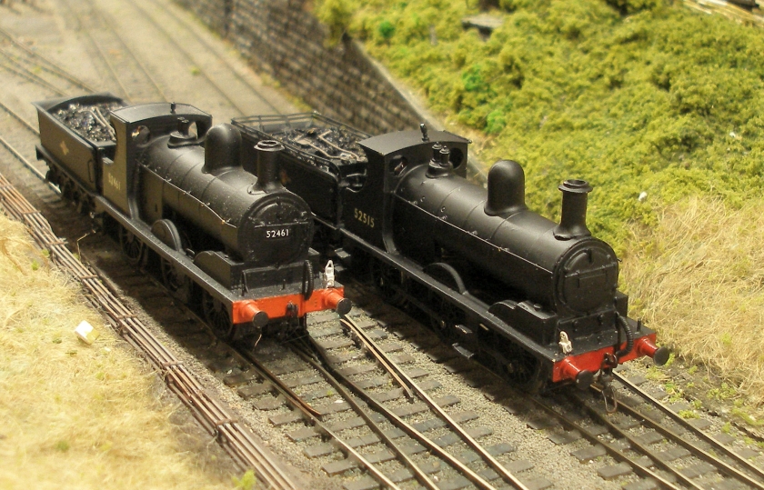
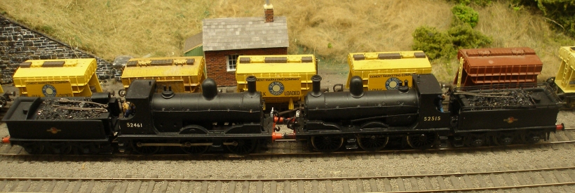
Now the big moment: how does the Craftsman compare to the 3D printed AJModels example? The AJModels is on the left; the Craftsman on the right.
Given the previously reported problems, how does the Craftsman run? There is clearly an electrical problem, as although it ran on the layout for 20 minutes without problem, the decoder suddenly got very hot, and then failed. A job for tomorrow, but looks like the electrics are going to have to be taken apart and each element carefully checked. This can't be an issue with the kit as such, but it something of a mystery.
I wrote the above too soon, as she then blew the decoder. There was clearly a short, and probably the Solder Mask had not been applied as comprehensively as it should have been on the wires connecting the loco and tender. I decided on a 'Keep it simple, stupid' strategy, and have been able to place the decoder on top of the chassis, where it is partially hidden by wheel splashers. I stuck the decoder to the chassis with double sided tape, and then painted the plastic cover of the decoder matt black.
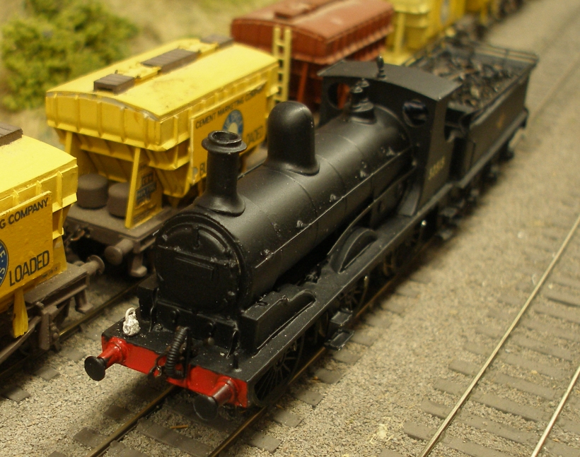
And this is what it looked like with the body in place.
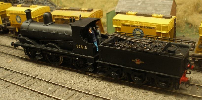
And finally some shots this afternoon to prove the success of the installation.
LYR 4mm scale models of Aspinall Class 27 0-6-0: AJModels 3D printed body on Bachmann Class C chassis on the left; Craftsman model on original chassis on the right
25 April 2021
Final thoughts
It is a nice kit to make, but there are some additional points to note. Some photos of the finished model would have been very helpful, especially when fitting the reversing rod.
Craftsman could have provided jointed rods, but the replacement Gibson Universal ones have worked well.
The designer also assumed a conventional motor with worm drive, and the lower cab floor is just plain wrong where this is facilitated. Shame that an alternative floor/backhead wasn't provided. I probably could have modified mine if I had given it more thought.
Although I didn't build the tender(s), one of my tenders had a solid floor for the tender tank, to which the wheeled chassis is bolted. It had been my intention to mount the decoder in the tender, but so far attempts to cut through the floor of an assembled tender have failed! However, the second one has an open bottom, and this would make fitting the decoder inside much easier if required.
What a shame Craftsman and its models appear to have completely disappeared, as this is an excellent kit, and would be a popular subject if available today.
Copyright J K Wallace, t/a 'Hall Royd Junction' 2013-2023 email: Hall Royd Junction
7 Portobello Close, Chesham, Bucks. HP5 2PL, UK
tel: +44 (0)7513 412880