
Minx Point & Signal Motor system
Motor - and solenoid - systems that have to be mounted and adjusted under the baseboard have never worked for me. So when I read about the Minx system which involved a small motor unit which could be mounted and adjusted above the baseboard, it seemed worth a try.
However, potential users should note that production of the system has been suspended as from April 2017, and the proprietors are currently seeking a new owner (October 2017).
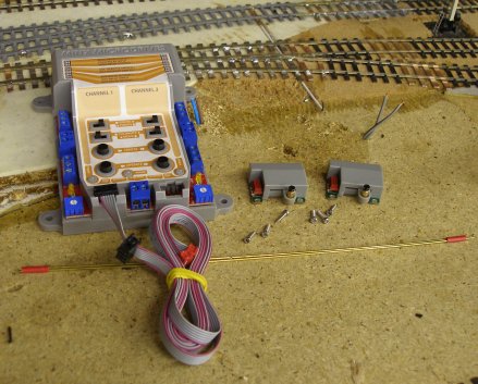
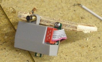
The Minx system consists of two motor units, two operating wires and a control unit. There are also two ribbon leads to connect the motor units to the control unit, plus six screws to affix the motor unit to the baseboard.
There are also comprehensive instructions. These appear rather complicated from a preliminary read, but hopefully these notes will answer the various practical questions as the installation progresses. What is neat is the use of the ribbon cable to provide a quick connection between the motor unit and the control module.
The control module carries out all the switching and control functions, and on the Minx Website is shown as being hinged under the baseboard so it can be quickly accessed for re-programming.
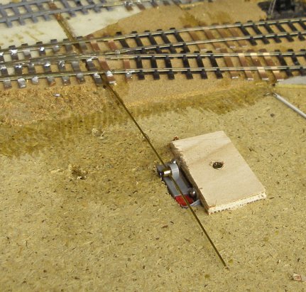
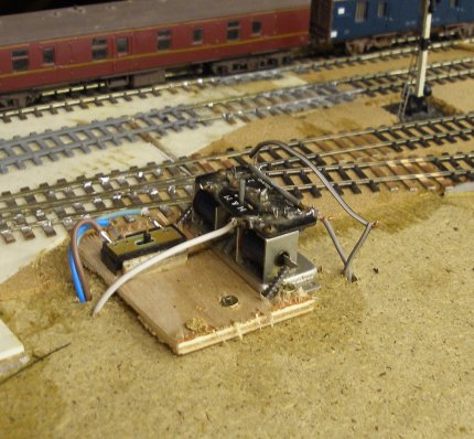
The Minx unit has been attached to a piece of 3-ply, so effectively forming an L-shaped unit using the small screws supplied. The motor unit can now be inserted into the hole into the baseboard, with the piece of ply now lying flat on the baseboard top. The ply is now screwed to the base board top, so firmly securing the motor unit. The assembly process to this point has taken exactly 30 minutes.
Now we come to the setting up. The instructions look long and complicated, and one suspects that enough of these have been sold for lots of silly things to have happened, leading the manufacturers to adopt a belt and braces approach to instructions!
It is very straightforward. In summary, the motor needs to be told where 'centre' is, and the points also set so they are split between the two roads before the control rod to the tie-bar is affixed to the actuator. After that, pressing the 'operate' button changes the points.
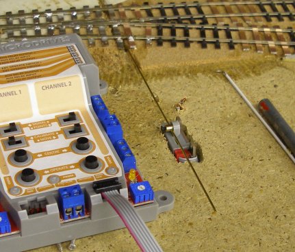
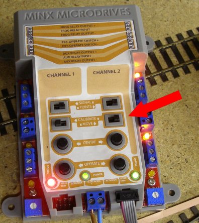
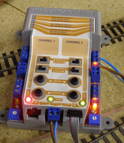
The photo shows the 12 volt supply wires have been attached to the two terminals at the bottom of the unit. As soon as power is connected, the unit lights up. With the motor connected (but the tie-bar not attached), the setting can now be undertaken. There are two buttons: Signal/Points and Calibrate/Move. Despite reading the instructions carefully, I failed to set the Calibrate/Move button correctly on the first go, so have arrowed it in the picture!
A prime example of reading something but the brain failing to take the appropriate action.
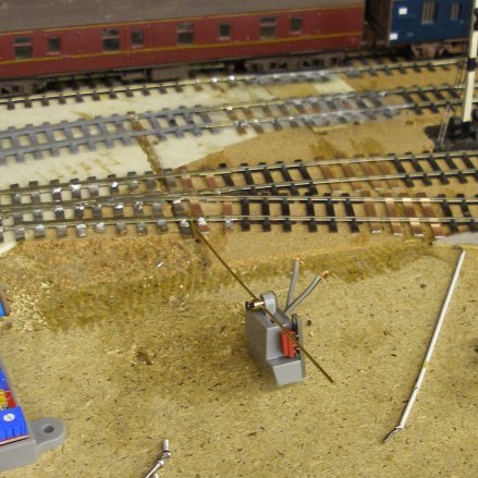
Now the actuator has to be set up. Remember, although the control rod is now inserted into the actuator mechanism, and connected to the tie-bar, the screw on the actuator has NOT been tightened, and the control rod is still free to move backwards and forwards.
So with everything connected and power on, select the Channel (either 1 or 2), slide the top switch to POINT and the one underneath to CALIBRATE, and press the OPERATE button. The actuator will move to one end of its travel. Press the OPERATE button again, and it will move to the other end of its travel.
Now slide the lower switch to MOVE and press the CENTRE button. The actuator will now move to the centre position. Now tighten the small cross-head screw on the output arm boss.
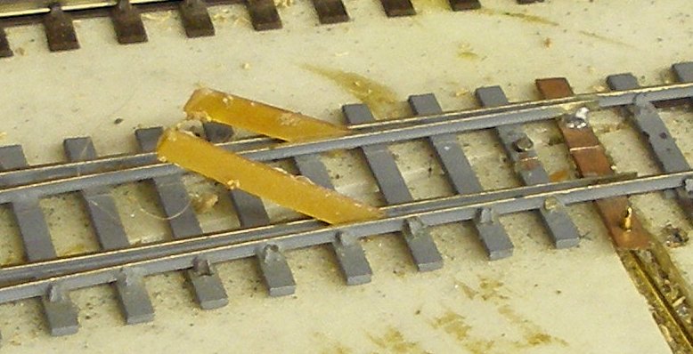
Put the switches back to POINT and CALIBRATE. Remove the packing pieces from the point, and press the OPERATE button. The blades should move till they are against the stock rail. Press OPERATE again, and the points will be reversed.
The speed of the movement can be adjusted - the control is at the bottom of the panel and needs a screw driver to adjust.
Two things to watch. The control rod mustn't have any pressure on it so needs to be bent to ensure that there is a 'clean' run between actuator and tie-bar, and when using the remote control facility with an on/off switch, you do need a 'good quality' switch. I initially used a DPDT slider switch, which obviously has poor internal mechanics, as the pair of pints then started switching every half minute or so. Replacement with a toggle switch cured this particular problem.
Having set up the points, it was time to wire up the live frog. In this case, it is the top row of three terminals that are needed, with the middle terminal feeding the frog, and the outer terminals taking the track power supply. Incidentally, I use 230 volt type wire for track supply (stripped out of its sheathing) to ensure a high grade DCC track supply, and this ONLY carries 12 volts, and is NOT connected to the mains.
What the designer has done is transfer all the relays and micro-switches that are normally part of the switch motor and placed them away from the point in a control unit. The bad news is that there is a bulky control unit to be put somewhere under the baseboard; the good news is that the motor unit itself is very small and compact. The other very good news is that all the wiring can be installed above the baseboard using easy-to-use screw terminals, and the actual installation of these units is fast and accurate.
The design is the complete reverse of the Tortoise/Cobalt-clone concept, where a very large box has to be installed under the point, whereas in the Minx system, the actual unit is very small, with the 'large box' 'off-stage' in some handy location.
I am delighted to report the movement was a delightfully controlled passage of the blades. Nice one!
There's more to do, and I'll write up further progress during the first week of October (second co-acting switch unit; delayed action of the second unit [so it looks like the signalman has had to pull the next lever in the frame], and remote operation from the 'real' control panel).
First thoughts?
At £42 for two points or £21 a point, it seems expensive. But on the floor of the loft are the remnants of the previous systems, with examples of Tortoise, Peco, Seep and H&M motors piled up in boxes waiting to go on eBay... So I have spent a lot more on rival systems which in the end didn't make the grade.
But I hate - really hate - having to try and align small steel rods through a hole in the base board with an even smaller hole in the tie-bar. And if a wire becomes unsoldered from the Peco PL-13 - or worse, the terminal actually break off because it is too light to carry the weight of the wiring - then usually it means taking everything down and starting again.
Likewise trying to get the blades to close tightly against both stock rails has always been tricky, and despite the warnings in the Minx instructions about ensuring the blades swing freely and easily, the little motor very firmly and positively drives the blades into place. A great plus of the system is the ease with which the SPEED of the blade switching can be adjusted - a world first? Even the Tortoise has a fixed speed.
The switching of the frog is again spot on, and one feels this is the result of a properly engineered control unit. Unlike the poor old Peco PL-13, which now seems to be suffering from a reduced specification, and modern units are not as reliable or as well made as the ones I bought in the 70s and 80s.
So the neat and easy to install drive combined with very positive action makes this my preferred electrical motor solution for points. For points nearer the control area I still prefer the method promoted by Hornby magazine using piano-wire rods, plastic knobs from Wilkinson and the brass bits stripped out of terminal blocks. In the storage sidings I have used DPDT slider switches directly linked to the point, as the business end of the storage sidings is handy for the control panel. So in the grander scheme of things, given that I have six points that are difficult to access, and around 22 that can be just as easily operated using manual switching, then the average cost per point is going to work out at £5.30 a point.
The Minx system also has a semaphore signal capability, including the facility for a bounce in the downward direction. This will be tested - but not yet! I've got to finish the points first.
The remote switching function - utilising a simple on/off switch which can be mounted on the central control panel - doesn't require much power to work it. The bad news is that it is highly susceptible to 'spikes' in the 12 volt DC power supply, which it detects as 'positives', and so appears to randomly change the points.
It was quickly discovered that my long-suffering H&M power packs were prone to spike production, such that they too have now had to be retired.
There are, however, a number of solutions. I have successfully tested the power unit out of a PC (there are a lot lying round the office after the Windows 8 upgrade forced the premature retirement of a number of Windows XP machines). The only 'problem' is that there is a softswitch activated when the PC is switched on. To get round this you need to find the green wire (there is only one in the output looms) and connect it to an adjacent black lead.
I had to 'test' three units before I found one that worked correctly: one needed to be have the green/black wire 'switch' reset each time power was applied, whereas I wanted power to be live when the loft power master switch was thrown. Another unit didn't work at all.
However the 12 volt supply is clean - as you would expect from something designed for a PC environment - and the Minx unit worked perfectly using it.
Option 2 was to tap the layout 16 volt bus, and rectify it using a Gaugemaster GM40 rectifier. This also worked a treat, but one of my Hornby sound locos suddenly made a loud cracking sound, and although it still works, there is no sound. A call to Hornby suggested that it is the loudspeaker that has blown. There is no obvious reason why it should, but this has left me thinking that I would like to keep the traction supply separate from everything else (so more wires under the baseboard - who was it who said you only needed two with DCC?).
I was concerned that there were still some H&M solenoid units being used in the adjacent sidings which were on the remaining 16 volt AC feed from the H&M transformer unit. They continued to work well when switched onto the 12 volt supply from the PC unit, so this has greatly simplified things with all accessory power now been taken from one supply.
I also dug out some 'modern' model railway transformers supplied by AMR in the last 10 years, but these too have been found to have spikes in the output. Back at the office in the IT draw were a number of Netgear transformer plugs rated at 16 volts AC (Part Number PWR-010-004). These were also wired through the Gaugemaster rectifier; the rectifier drops the voltage by two volts so the final output is 14 v DC. Sadly, these also appear to produce an output with spikes.
This issue does highlight how the model railway hobby is rapidly leaving the solenoid/DC age, and that gear that was previously perfectly acceptable now needs to be reviewed for its 'fitness for purpose' on a contemporary layout.
Finally, how robust is the Minx system? Only time will tell, but first impressions are very good. Highly recommended for anyone who hates setting up things under the baseboard.
There is also a DCC option, and the instructions are here.
Final wrap up
This is the final report on the Minx, dated 20 October 2017.
I have now replaced the system with a conventional DCC Concepts Cobalt accessory decoder with CDU and solenoid.
The primary reason for this was that my DCC layout had moved away from the simple '2 wires concept', and at one point there were three sets of bus wires/power supplies: one for the traction bus; a clean 16 volt supply for working solenoids and then a clean 12 volt supply for the Minx!! It took some time to find a suitable 12 volt transformer for the Minx as it needed a supply without spikes, and in the end a redundant power box from an old PC did the trick. However, as this came in a box with a fan, it was subtly intrusive, and rather detracted from the railway room environment.
Secondly, the Minx system allowed each point to be individually set, so that the actuator powered down as the blades made contact with the stock rail. Latterly, this seemed to needed to be re-set each session, and there came a time where the points (and associated tracks) were not being used. The two points were initially set-up to be co-acting (so both switched together). However, in my set-up - and despite following the instructions carefully - this never worked, and the points had to be set individually.
The units were going to be worked remotely by analog switches (so more wires running down the layout and across joints). Switching them this way, It was sometimes difficult to tell whether the points had actually been moved, and there was also a question mark as to whether the frog polarity had been changed. Locos often stalled on the point, although it without the loco, it seemed to work. If confronted with this particular problem now, I would try powering the frog with a Hex Jucier and not get too stressed as to whether the Minx was working correctly.
Finally, it has to be said that the command units were somewhat bulky and were very prominent on the baseboard fascia. I could have probably wired mine more neatly, but there were a lot of wires poked into various terminals.
In an attempt to simplify things, I bought a couple of the Minx DCC plug-in units. Again, results were mixed. I could programme the first of the two channels to work successfully, but couldn't get the second to work at the same time. If the second was programmed, the first needed re-programming, and so on.
The actuators, however, worked as advertised.They were easy to fit, and were perfectly capable of working, and locking, the copper-paxolin points with their sprung blades.
But what probably did for Minx was the arrival of servos. These are stock items available from multiple sources and have been widely adopted, particularly for working signals. Personally I think the Minx actuator is superior in terms of compactness and drive line.
In the final analysis, the Minx introduced complexity to the layout, and the march of technology has seen neater solutions present themselves.
Whilst this testing and development was going on, other parts of the layout (behind the scenes) were being equipped with the tried-and-tested PECO solenoids and points (both the green solenoid 1.5 Amp type and the low-profile PL-11) in conjunction with the DCC Concepts Accessory Decoder CDU Solenoid Drive SX 2-Way with power-off memory and protective case (ADS-2sx). The beauty of this arrangement is that the accessory decoder charges from the traction bus, and does not require an independent power supply. It fires the solenoids reliably, along with frog polarity. This combination of elements is more compact, although the Minx scored in the compactness of the actual actuation mechanism (even smaller than a servo) and the fact that it operated copper-paxolin built points with their sprung point blades as it could both drive the blades across and 'lock' them reliably at the end of their travel.
The final nail - ironically - was the announcement by PECO of the launch of their British track and point system, which meant that a PECO point can finally be laid in the viewable area, and worked conventionally. And, at the end of the day, I only need one point to be worked like this. Therefore the decision has been taken to remove both the Minx system and the original point.
20 October 2017

Copyright J K Wallace, t/a 'Hall Royd Junction' 2013-2023 email: Hall Royd Junction
7 Portobello Close, Chesham, Bucks. HP5 2PL, UK
tel: +44 (0)7513 412880