
Signals for a Model Railway
Every good layout needs signals. And the first port of call is a signalling diagram.
So far, a copy of the original Hall Royd diagram has not yet surfaced, but it has been possible to piece together a 'replica' using elements from other original signal box diagrams thus:
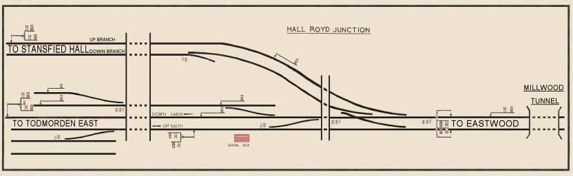
This needs the lever numbers adding, and should also show more track to the east, as there is an Up distant bracket and down Intermediate Block Signal in the Eastwood direction, as well as an electrically worked gong in Millwood Tunnel. This also does not show the track circuits. However the layout is for the BR period up to late 1965/early 1966 when the single slip and the Up bracket for the Up Passenger Loop was removed.
The signal production line was forced to take a holiday, primarily due to difficulties finding good images (or any images) of some of the key signals.
The first signal produced in the current batch is the bracket controlling access to the Up Passenger Loop which used to stand between the signal box and Hall Royd Road bridge. The photos show the current state of development, with the platform and laddering in the process of being added.
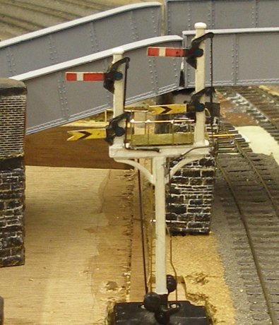
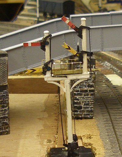
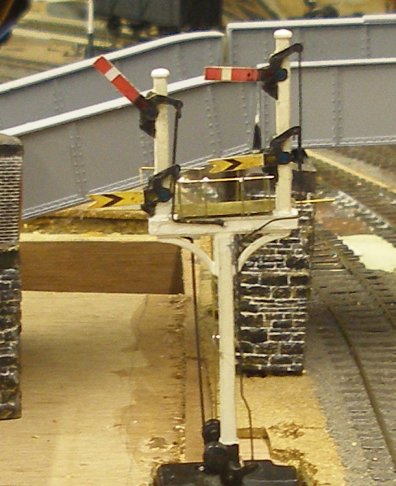
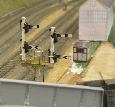
The signal is a L&YR post, with LNWR caps (replacing the LYR finials) and LMS upper quadrant arms. The model is something of a cheat in that it utilises a Hornby Dublo 2-arm solenoid base and bracket post. However these are a striking 'match' for the prototype and it can only be conjectured that Frank Hornby modelled the signals he saw at his local railway station as they were in 1937...
As there are only two actuators available, when the signal is set for the 'main' both the home and distant are pulled, whereas for the Up Passenger Loop, the distant is fixed and only the Home is pulled off. Of course, the reality is that the configuration of the dumb-bell loop beyond the bridge means that the Up Loop couldn't be included, so this is a rare instance of the full set of signals being modelled but not the track; many modellers tend to put the track in and not the signals!
It may be difficult to see in the photos, but it is possible to solder the backlight blinders to the Hornby spindle so that they work. Hornby Dublo were surprisingly ahead of their time, and if they had found a way to punch the holes for the spectacles in the arms, they would have been very close to producing a ready-to-fit scale model.
The platform and railings are from scrap brass and Alan Gibson straight wire, whilst the ladder is a Langley product. The signal arms are from a Spratt and Winkle fret, and the arms themselves are decorated with our own transfers, available for purchase on this site...
After much experimenting with modern servos and Dapol-style actuators, I have come back to the HD solenoid on the basis that it is a compact design, and very reliable. In short, I think they are a very cost-effective - and effective - way of powering signals.
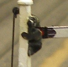
This photo shows how the back light blinder has been affixed to the original Hornby Dublo spindle. First, the spindle end is cleaned up with a file, and then tinned with flux and solder in the normal manner. The back light blinder was removed from the Spratt and Winkle fret, and the end which engages with the spindle also tinned. The two are then brought together, with the soldering iron, and a pretty robust join is the result. These work exactly as intended.
Also note in this view how the transfers provide the detail on the rear spectacle plate, and also the appearance of a folded lip along the top of the arm.
Still to be added is the planking on the platform (parallel to the rack) and the ladder to the top lamp. To prevent fowling the arm, this is offset, so attached to the back of the post.
Copyright J K Wallace, t/a 'Hall Royd Junction' 2013-2023 email: Hall Royd Junction
7 Portobello Close, Chesham, Bucks. HP5 2PL, UK
tel: +44 (0)7513 412880