
Construction of a Hi-Level Gear Box
The quest to find an easy to construct and fit motor and gearbox has been something of a challenge since the demise of the Keen Maygib/Portescap RG4.
I have tried a number of gear boxes from a variety of manufacturers - usually tied to a Mashima - but with little success.
The Hi-Level range of gear boxes appeared to be well liked by many, and I thought I would try one. I bought two boxes at Railex in Aylesbury - one with a motor and one to fit to an existing motor.
These notes relate to the second one, the first being something of a guinea pig, and therefore these notes show how it should be done.
Hi-level have an excellent Website which shows how the various boxes and motor combinations fit into a range of different loco types. For this first exploration I kept it simple and used the RoadRunner. Although many modellers favour the low gearing to give maximum torque and low speed, I have found Mashima's with low geared boxes too slow for my needs, so for this assessment has used 1 in 30 gearing.
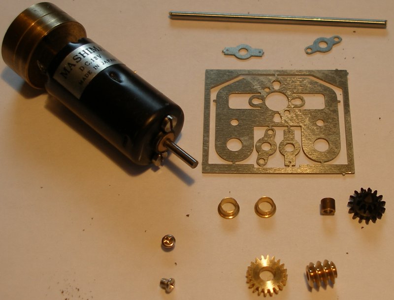
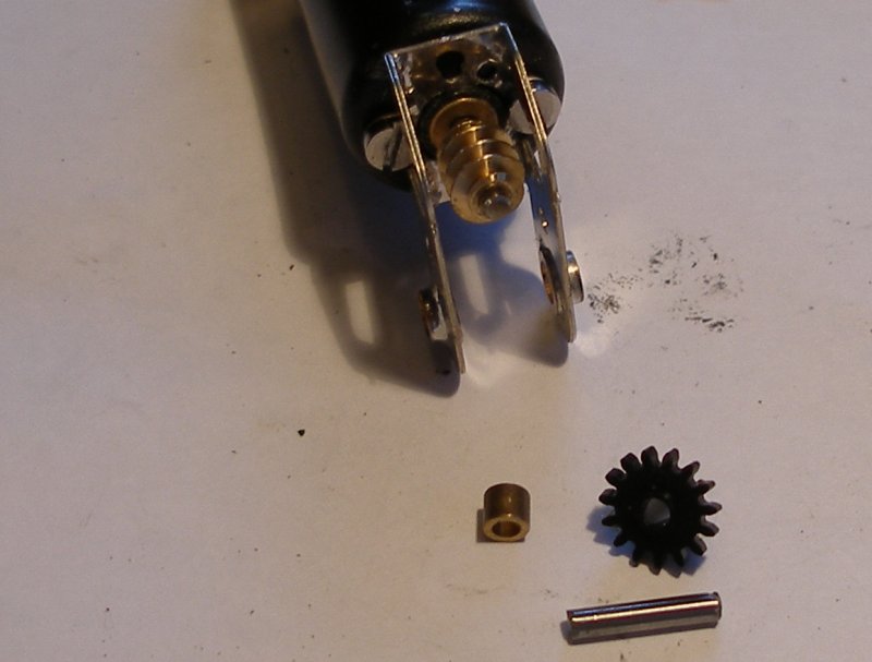
The image below shows the contents of the small bag, and the Mashima motor taken from my stock. This is going to be assembled conventionally, so the parts for the extended drives will be discarded.
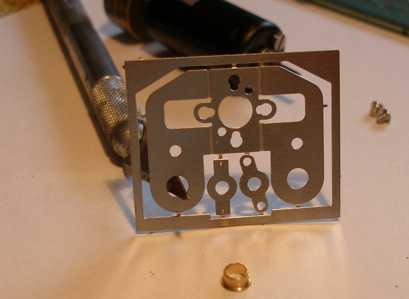
First part of the operation is to gentle ream out the holes in the fret that are to take the axle bearings. I have used a scalpel in the image below, but there are better tools for the job.
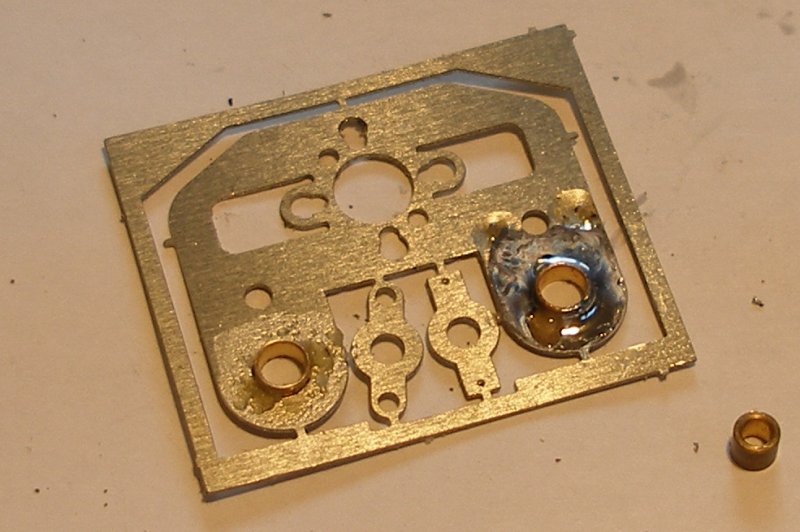
Having gentle opened up the holes so that the top hat bearing just fits, the bearings are pushed trhough from the side with the fold lines, and soldered in place. In the instructions it is suggested that the raised part of the bearing is filed flat. However I found it helpful to file these so that the whole assembly is a comfortable fit between the frames, and therefore this operation was left to later
With the bearings in place, the sides are folded up. Note that the etch lines are on top, and that a pair of pliers have been used to keep the sides straight.
With both side s folded, the drive shaft is fed through the appropriate set of holes to check alignment.
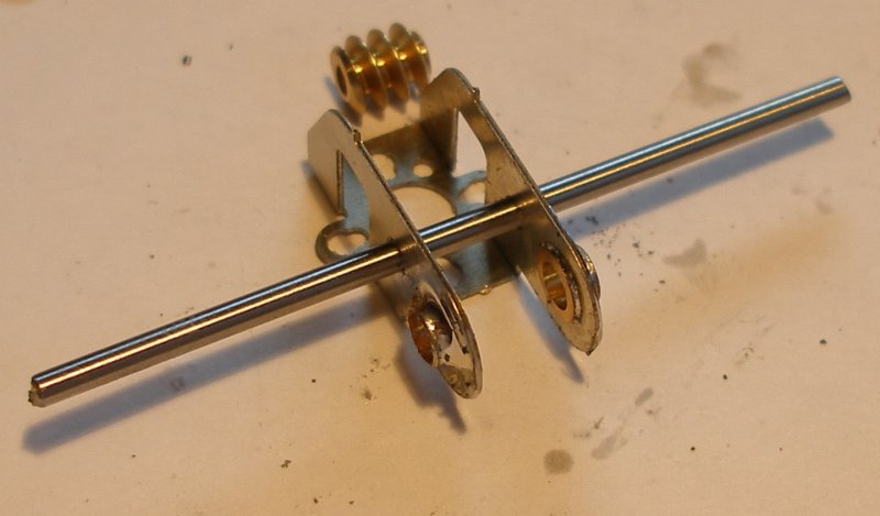
Now a reinforcing fillet of solder is added to both the inside folds of the gear box, top and bottom.
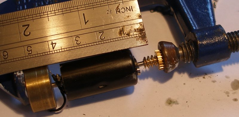
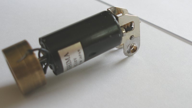
With the initial assembly complete, now it is time to tackle the motor. The motor is too long for my mini-vice but it is possible to use a wood working client. The worm fits onto the end of the shaft quite neatly but needs to be propelled along the shaft. The instructions show the middle of the worm should be approximately 6mm from the front face of the motor. The final gear has been used here as a spacer, so that the worm gear can be fully pushed home.
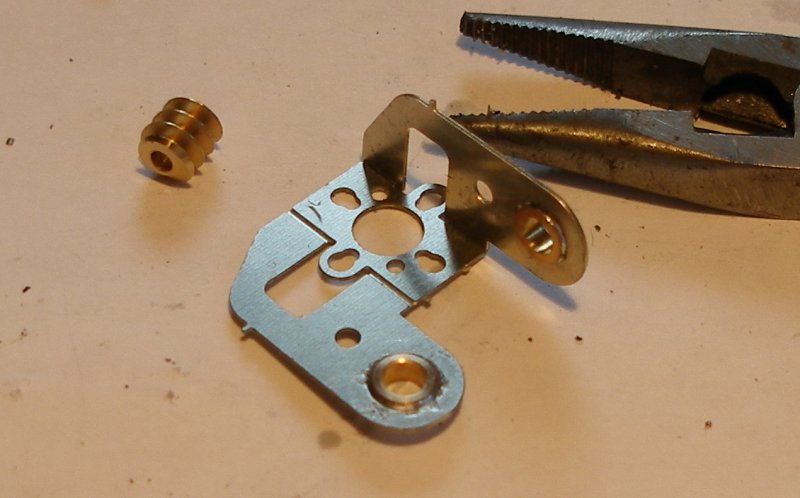
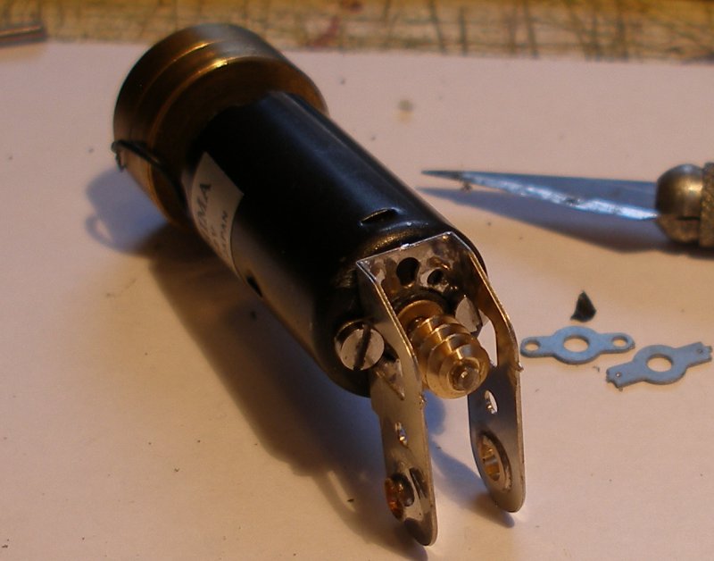
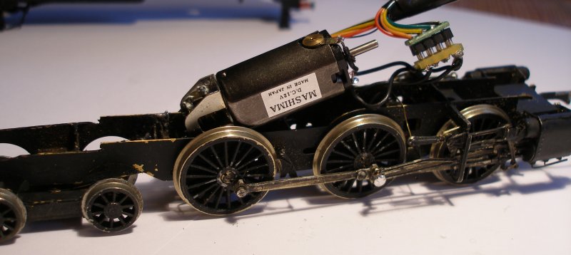
A neat aspect of the Hi-Level box is that three sets of mounting holes are provided. The instructions suggest that the pair of holes ranged left and right (so at the sides) be used to secure the motor. Unlike the Portescap motor and gearbox, the wheels cannot be rotated once the box and motor are installed, However Hi-Level note that if these screw fixing holes are used, the gearbox can be left in the chassis and the motor removed so allowing checking and tweaking of the chassis. The screw holes for this particular motor were a perfect fit. However the motor had a raised boss, the hole through which the worn is inserted had to be enlarged before the gearbox was a snug fit up against the front of the motor. The image below shows the box now screwed to the motor.
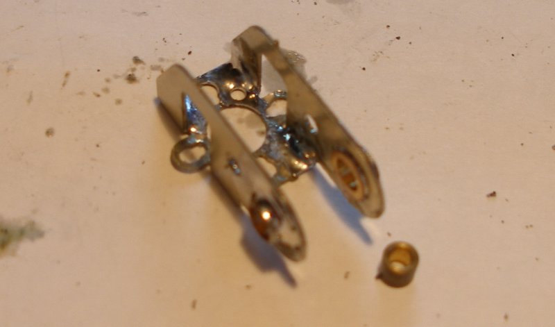
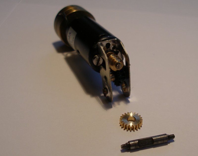
The intermediate drive shaft now has to be cut. I found it was best to cut this slightly wider than the assembled gear box. This is because in the first one I assembled the shaft became dislodged after assembly and one end dropped inside the box after the Loctite 603 had been applied, but had not fully cured. I did not spot this when mounting the box in the chassis, and it was only when the initial running of the completed chassis proved disappointing did I spot the fault. The problems of dismantling a completed and installed box are discussed below. The image below shows the plastic gear wheel and the brass spacer ready to be fed onto the shaft. The instructions suggest a cutting disk held in a mini-drill to cut the shaft. I was able to cut it using the Xercon rail clippers. The ends of the shaft were then filed flat.
The image below shows the draft shaft assembled, with, from left to right, the brass spacer and then the black gear wheel. In the first box I assembled, the shaft passed easily through both the spacer and gear wheel, but in this, the second one, it took a fair bit of filing and reaming to pass the shaft through all the various parts. Note how the end of the shaft is proud of the gear box side.
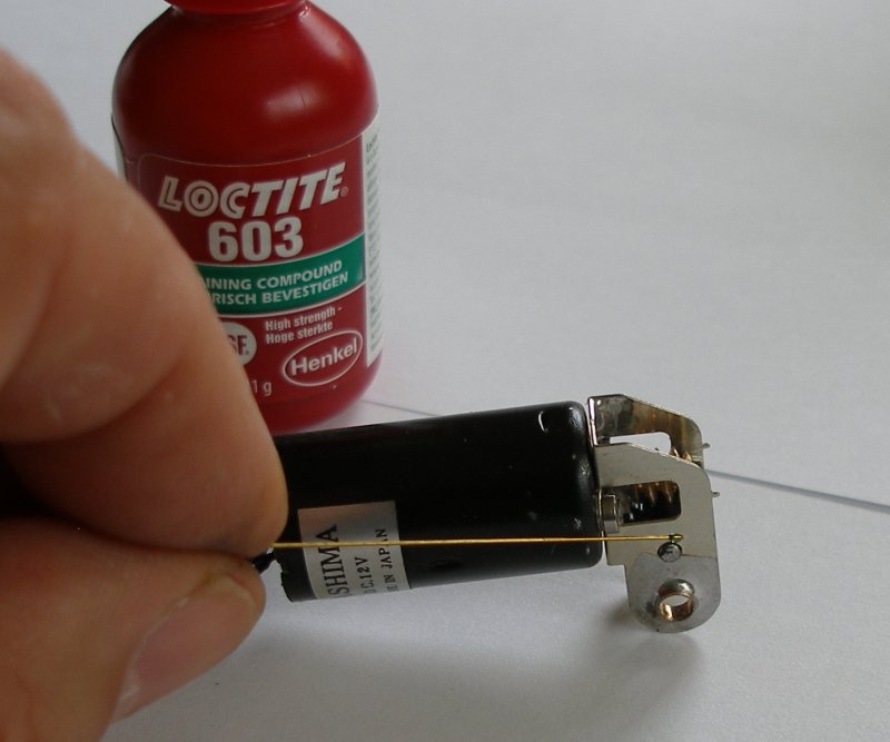
Finally, the Loctite 603 comes into play, and in the image below is being sparingly applied using a thin wire. The whole assembly will now be put aside for 6 hours to allow the Loctite to fully cure. Incidentally, it would also be possible to solder this axle in place, however I was concerned that any heat applied here would melt the plastic gear wheel.
Now with the Loctite having set, the Romford axle and gear wheel are now ready to offered up.
With the axle gear wheel assembled, note the small air gap between the black plastic gear and the brass gear wheel, as noted in the instructions. It is difficult to see this gap when the gearbox is between the frames and before the final Loctite is applied to secure the brass wheel to the axle. I will place a piece of thin card into the gap when finally placing it in the frames, and only remove it after the Loctite has fully cured. The completed motor and gearbox is propped up on the remains of the old gear box. As can be seen, to remove it, it had to be cut open as the screws securing the motor where literally built into a sealed unit, with the lower screw obscured by the gearing.
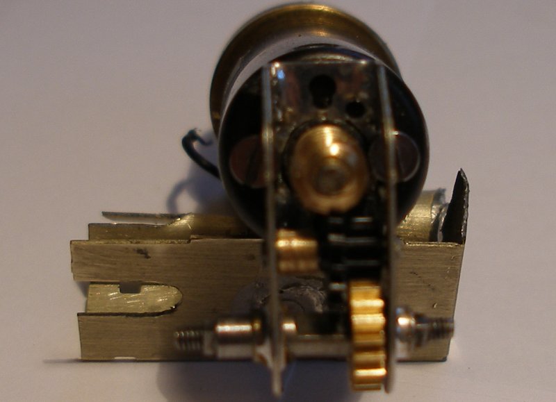
And here is one I made earlier. This is the first box I assembled. Note how the motor is wider than the frames, and therefore is at a rakishly inclined. This is not an issue in this loco, but worth noting when selecting a gearbox type from the excellent Hi-Level Website guide.
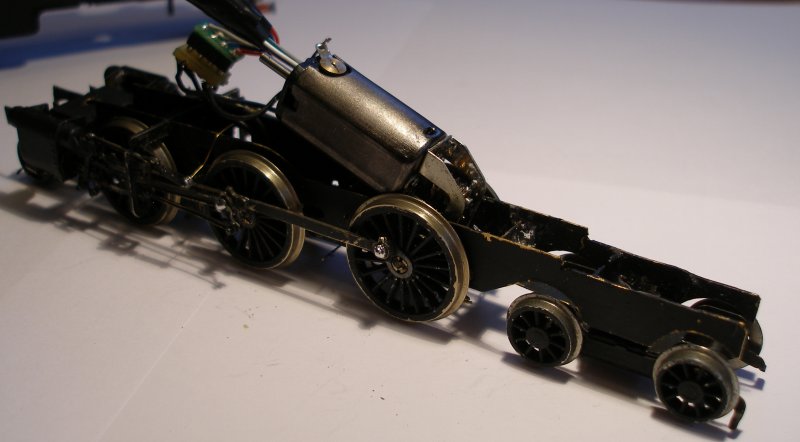
And almost ready for the road... The loco runs smoothly and powerfully even with that irritatingly bent radius rod!
Discussion
In summary, it is a neat design that provides a degree of flexibility when mounting. It requires 'moderate' technical skills to assemble. I followed the instructions and applied fillets of solder on the inside surfaces, but this is not strictly necessary if the builder is not a competent solderer.
I have a concern about the permanent assembly using Loctite 603. Once built and placed in the loco, there is no way of removing it without destroying the loco. Likewise, should the loco be scrapped at some future date, the box cannot be recovered and reused. However, if you use the outer motor-fixing screw holes, then it is possible to remove and recover the motor. So the gearbox is mounted in the loco 'for life', and therefore loco builders should have completed all the mechanical work and ensured they have a perfectly smooth running chassis before fitting the gearbox.
The most fiddly aspect of the design is assembling the intermediate drive shaft, as the shaft has to pass through the outer wall of the box, through the black plastic gear wheel, the brass space, and then through the other wall of the box. So any extra length in the shaft is helpful. However it cannot be too long, or it will foul the loco frames.
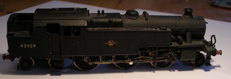
The first box - having been corrected - was placed in a Nu-cast white metal Stanier 4MT tank with a Comet chassis. This body provides plenty of weight, but there is also some extra lead for good measure. The loco runs quietly and smoothly. Crucially the motor was able to turn the wheels when the loco was run up against the buffer stops.
There has been much discussion in the forums as to whether the Mashima/Hi-Level combination is superior to the Portsecap RG4. The Portsecap comes ready made, and can be installed very quickly. It's final gear drive is fixed with a grub screw, so facilitating removal. And it is possible to rotate the wheels to check the operation of the chassis without having to remove anything. Generalkly they run well and have plenty of power.
However...they haven't been in production for some years now, and the later ones are noted for their noisy gearing. More crucially the ones now offered 'new' on eBay are pushing £100.
This compares to the Mashima/Hi-Level which retails at around £45 and is immediately available. A larger range of motors and box configurations are available, so giving the builder great flexibility than the original 3 types offered by Portescap (although there are alternative sides available). I have to say that running the loco with its new box, it does seem to be every equal of the Portescap in speed and controllability. It also - very marginally - seems quieter, and this may be due to the plastic gear wheel.
My only 'concern' is the use of Loctite to secure the gear wheel to the loco axle, so permanently fixing the box into the frame. However, the good design does mean the motor can be easily recovered.
In conclusion, I was able to build these boxes, and they ran well with minimal fettling. This compares to the pair of Comet boxes I tried some years ago, and which I could not get to mesh correctly.
Recommended!
Dismantling
As noted above, I had the challenge of removing the completed box from the chassis re-affix the chassis. Fortunately there was sufficient friction between the gear wheel and the Romford axle that it had run without the application of Loctitie. In theory, this should have allowed the easy removal of the axle, and then the box. Suffice to say, even with the Loctite, it proved very difficult to withdraw, and in the process the threading on the end of the Romford axle was destroyed. However, the box was successfully removed, and because the shaft had become dislocated during the curing process of the Loctite, it was not actually secured, so it was possible to position the shaft correctly and re-apply the Loctite.
The bottle of Loctite provides plenty of health warnings, but no instruction. However Loctite does have very comprehensive instructions, complete with a chart of curing times. An application will be fully cured within 12 hours.
Interestingly the motor and box did run with the shaft not properly engaged. However it was apparent that not all was well, as the motor was running very hot.

Copyright J K Wallace, t/a 'Hall Royd Junction' 2013-2023 email: Hall Royd Junction
7 Portobello Close, Chesham, Bucks. HP5 2PL, UK
tel: +44 (0)7513 412880