
The Hall Royd Gallows Signal
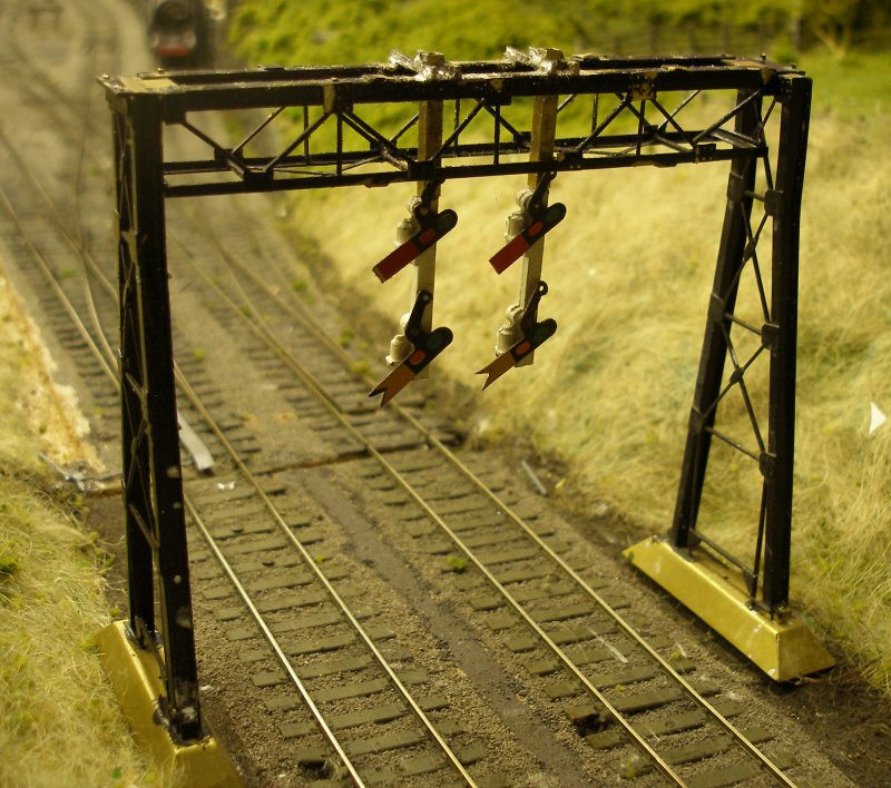
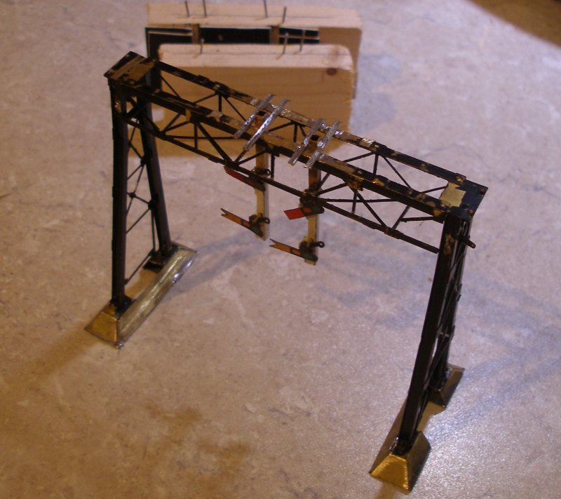
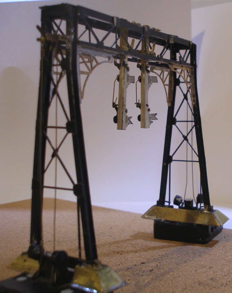
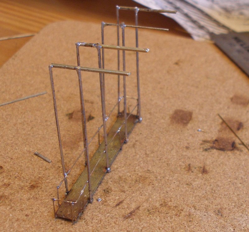
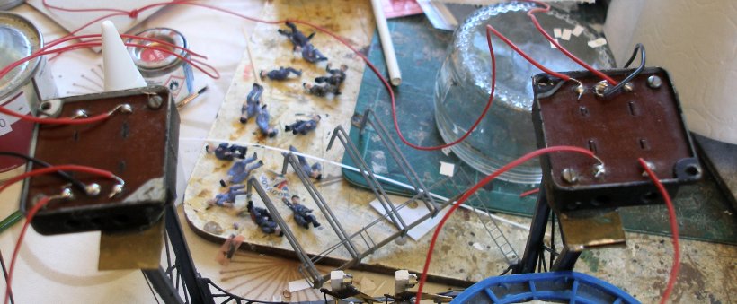
The gallows signal is the most challenging signal on the layout. The image below shows the two Hornby Dublo donor signals and the now out-of-production HO brass NJ International #4010 two track signal bridge, with reference photos.
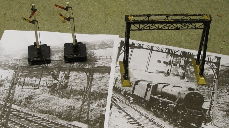
The gantry is not strictly accurate, as it uses a US product which is for the US-pattern 'Warren' truss girder, as opposed to the 'Pratt' type preferred in the UK. Comparison of the two showed that there are too many vertical members and some of the angled struts slope the wrong way. However, it does give a fair representation.
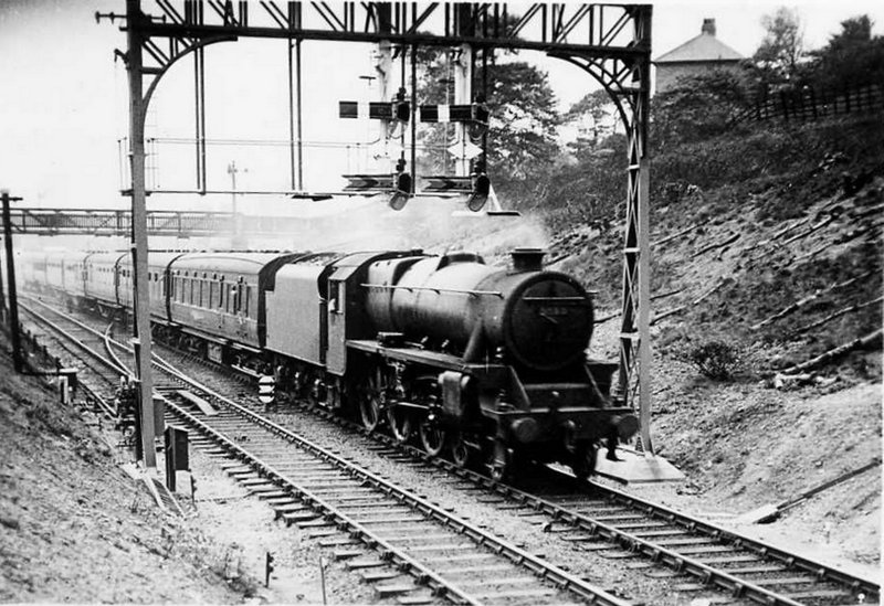
It had been assumed that this was an original L&YR structure from the Hall Royd widening of 1904. However, one of the photos obtained of the structure c. 1936-8 showed it with lower quadrant L&NWR arms. More critical study of the photos suggested that it was, in fact, a London & North Western Railway signal gantry, presumably erected sometime after Crewe assumed responsibility for signalling in 1922. Given the widening was undertaken in 1904, this suggests a very short life for the original L&YR structure that would have been here. The Hall Royd two-track gantry would have been one of the smallest configurations of this structure; the largest - and best known - was the one at Rugby, which was on two levels, and spanned multiple tracks, and so required four bridge structures. Remarkably, it was not unique on ex-Lancashire & Yorkshire Railway lines, as there was an almost identical structure located at the northern end of the Low Moor complex, next to Low Moor signal box No. 1 and also located at a tunnel mouth.
When checking the MSE Website for suitable cast-iron brackets, I discovered that MSE had an etch of a L&NWR bracket that was, to use the technical term, identical.
There may have been other similar gantries on LYR lines, as the LMS inherited a number of LYR wooden gallows signals located at tunnel mouths around the system. Certainly there was an identical unit guardian the entrance to the Low Moor station area which survived into the early 1960s as the image below shows.
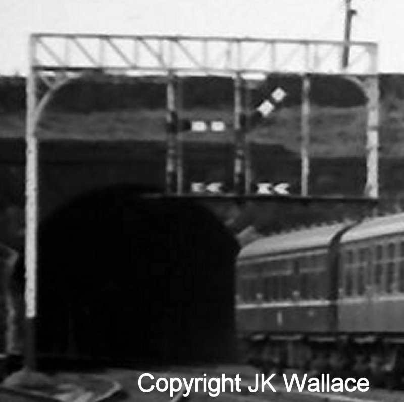
Copyright JK Wallace, all rights reserved
27 November 2016
The first move was to reduce the two Hornby Doublo donor signals into the required sections. First, the arms were trimmed back - yep, I used the kitchen scissors! The home signal is trimmed with a slither of white showing. The distant arm is trimmed so that the black chevron forms the trim guide for the cut out.
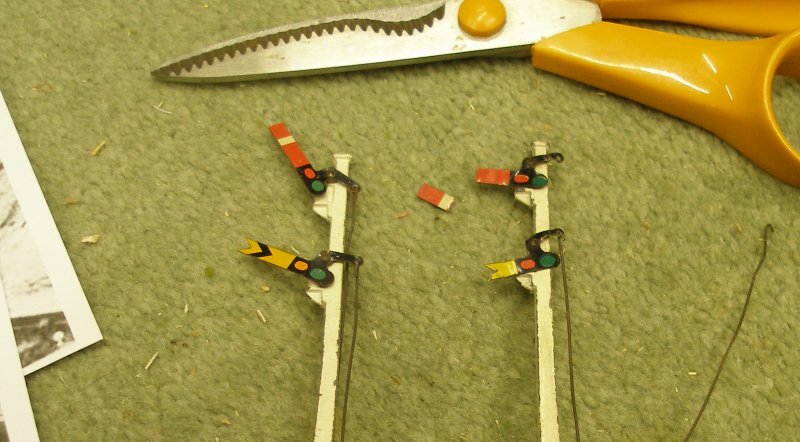
The signals are now cut into four parts, viz the base with balance weights; the section with the two arms; and finally, the caps are carefully cut off. These are a LNWR item adopted by the LMS when removing the original pre-grouping finials. In the photo, one of the caps has gone walk about.
The post carrying th arm needs to be extended upwards, and a peg is gentle formed with a file at the top of the post. The K&S 1/8th square brass tube is a dead match for the Dublo post, and not much filing is required to get a snug fit.
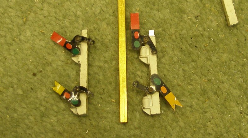
Finally, a spot of superglue is fed into the end of the tube, and the peg gentle pushed into it to create the extended 'doll'. The assembled dolls were then left to fully cure.
Struts now need to be soldered to the tops of the two dolls at right angles to the signal arms, one on each side of the doll. These should be made of angle iron, but not having any suitable section to hand, short sections of bull head rail were used. The complete sub-assemblies were then soldered to the top member of the gantry gross-beam.
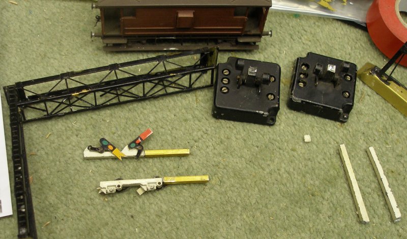
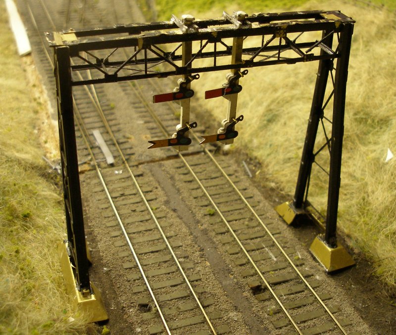
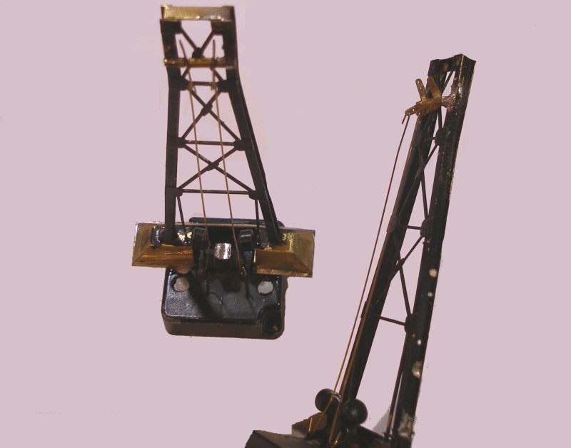
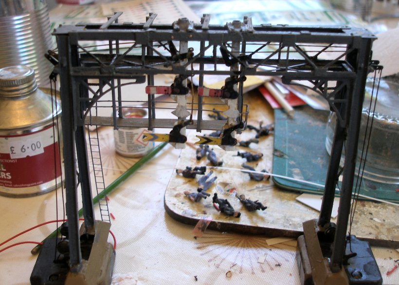
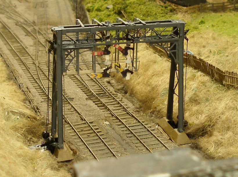
The following shots show the NJ International #4010 two track signal bridge with the dolls in position temporarily placed on the layout.
28 November 2016
A problem with working signal from the base via two cranks is ensuring that the arm is correctly aligned when in the 'on' (danger) position, as there is nothing worse than a drooping arm. It was therefore decided to fit arm stops.
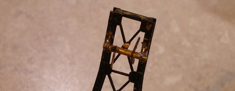
A hole was drilled through the post at the point the arm stop needed to be inserted. Gibson 9mm wire may seem somewhat heavy duty, but it has to be strong enough not to distort in service.
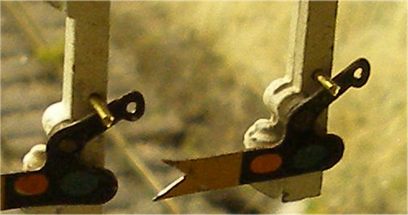
The rod has not yet been cut to length, as previous experience has suggested that it is best to leave final fettling until the signal is fully operational.
The original Hornby Dublo post caps have been superglued to the tops of the two dolls.
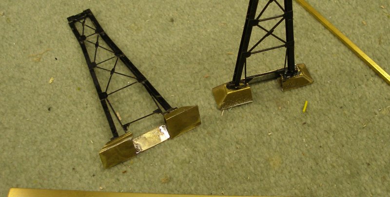
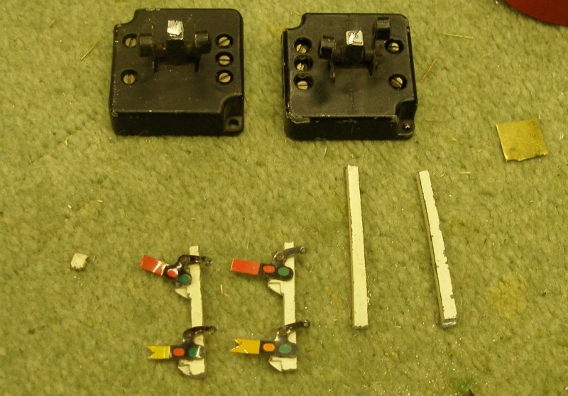
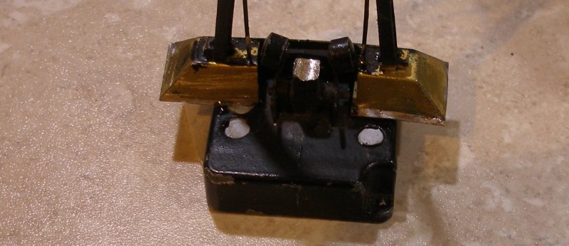
Sections were now cut out of the bases to allow the operating mechanism to be located directly under the upright supports. Also base plates were soldered onto the bottom of the bases, so that the base can be readily glued to the top of the Hornby Dublo mechanism housing.
Finally, the bases are trial assembled. It will be apparent that the signal bridge bases will cover the terminal screws, so making attaching or detaching the wires difficult. However, a better way to wire the signals is to solder the wires directly to the solder tabs on the bakerlite baseplate, and so avoid the need to use the screw terminals. The holes in the base plate can then be filled with some form of non-permanent filler such as Blu-tack.
29 November 2016
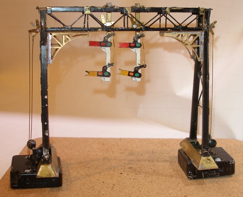
In Iain Rice's Tring Cutting article, Iain had centered the dolls on the gantry. From the initial study of the Hall Royd photos, it had been assumed that the dolls were mounted at the front of the structure. Further - more critical - study showed that the Hall Royd dolls were also centered!
However, one of the benefits of this prototypical arrangement is that the operating cranks for both the home and distant arms can be mounted either side of the doll.
Attempts to reposition the dolls 'freehand' proved very difficult, as previously the rear of the front truss had allowed the doll to be placed accurately.
A simple jig was therefore fashioned out of a couple of 2" x 1" off-cuts and some card.
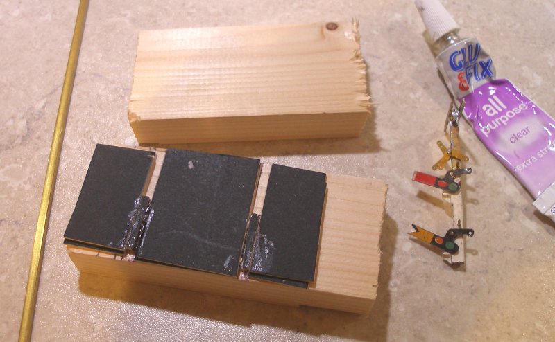
The total construction time to make the jig was just 10 minutes - a fraction of the time spent the previous evening trying to reposition them freehand!
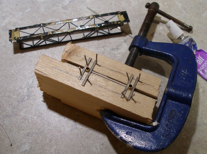
And literally two further minutes with a hot iron, and the reworked dolls can be trial fitted. This time round the cranks are going to be fitted, along with the operating rods between the spectacle plates and cranks BEFORE fixing the dolls permanently.
The next task was to fit the angle cranks and their associated brackets. Iain Rice in his article and Derek Mundy in the MSE instructions talk about larger sized bearing giving more reliable operation. The crank holes were then enlarged so that a piece of Mercontrol tubing could be used as the bearing, and then larger sleeves cut from a piece of handy spare tubing. The arms of the doll were also rodded up.
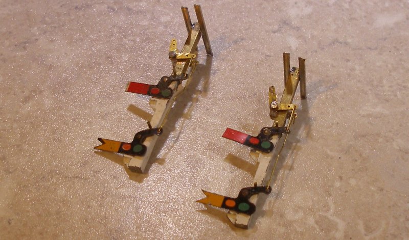
The cranks of the tops of the two uprights were also soldered into place, these being on the outside of the structure.
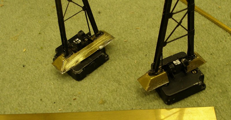
Finally the bases were Aradited to the Hornby bases, ensuring that the balance weights move easily. Note how the holes that contain the terminal screws have been filled with Blu-tack. The idea is that this will stop Araldite locking the screws in permanently should they need to be re-purposed at a later date. The standard, 24 hour setting Araldite was used to ensure a strong bond.
5 December 2016
Two of the MSE LNWR/LMS signal packs were acquired (S008/2W). The three parts of the bracket were cut out and then soldered together. They were then clean-up with a file.
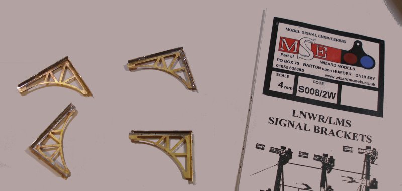
The kit also contains pieces to form various landings, and these were put to one side as a possible source for the access platform.
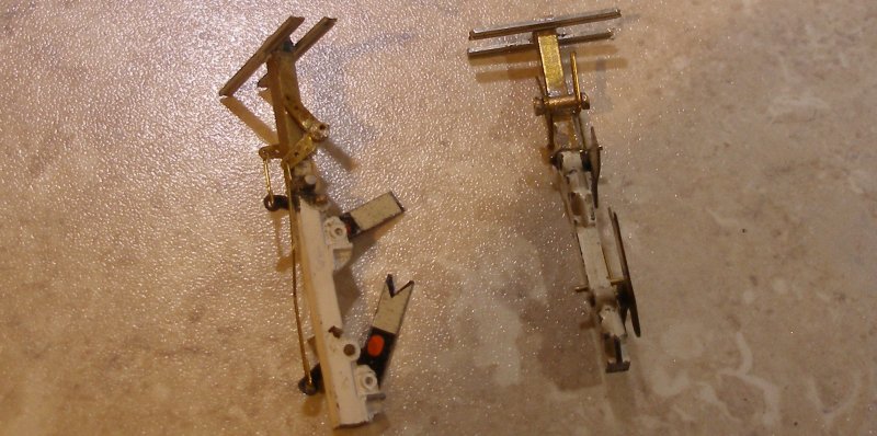
Next the cranks on the two vertical supports were rodded-up. The bottom of the rod were kinked inwards to avoid the balance weights - an idea copied from the original Hornby Dublo originals.
Finally the brackets and dolls were tack soldered into place.
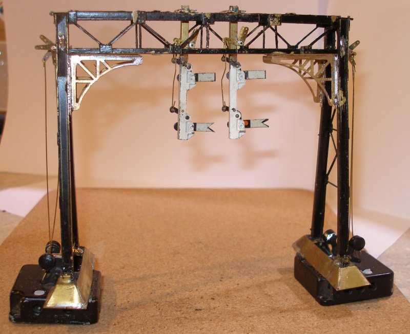
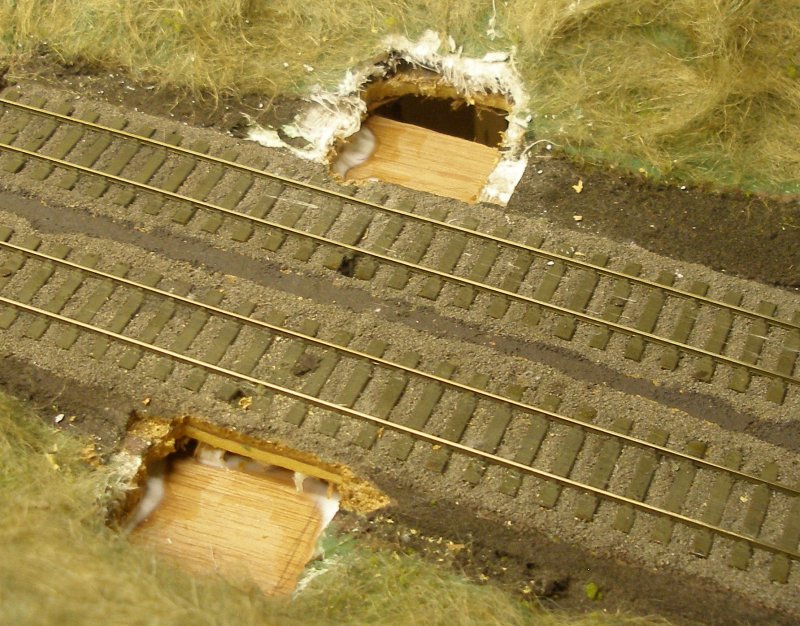
The photos show about an hour's worth of modelling time in which the final rodding runs were fitted (so meaning the signal can now be operated by its solenoid motors) and the holes cut for the motor mechanism pockets.
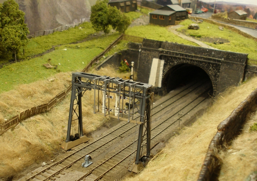
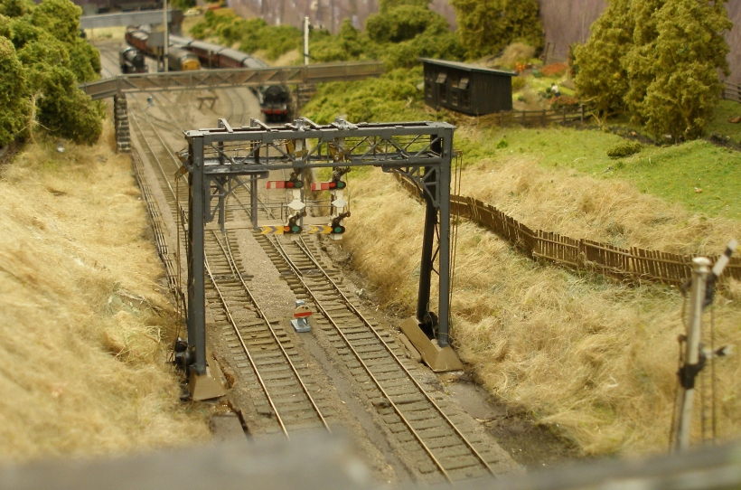
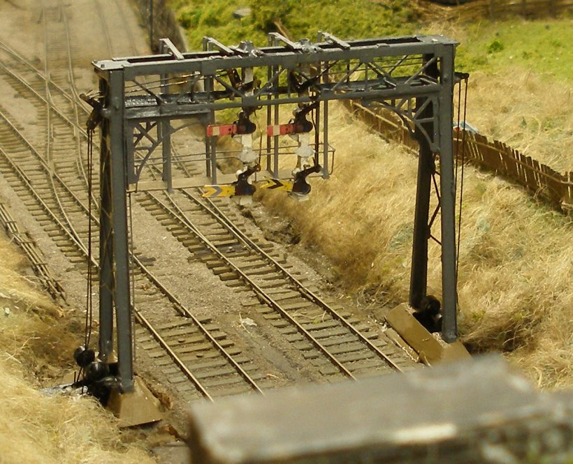
With the holes cut in the baseboard top, it was possible to try the gantry in its final location. This had been determined by counting the sleepers from the toe of the king points.
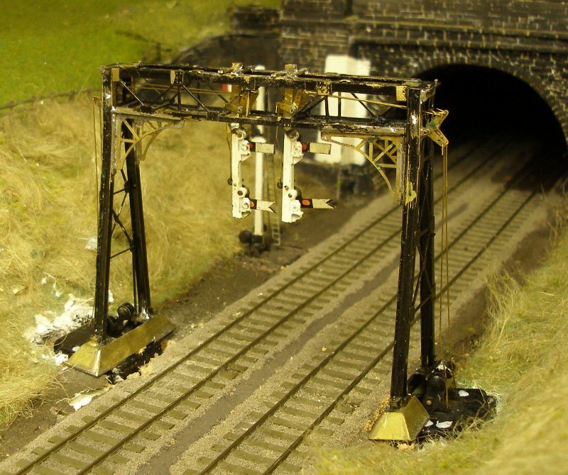
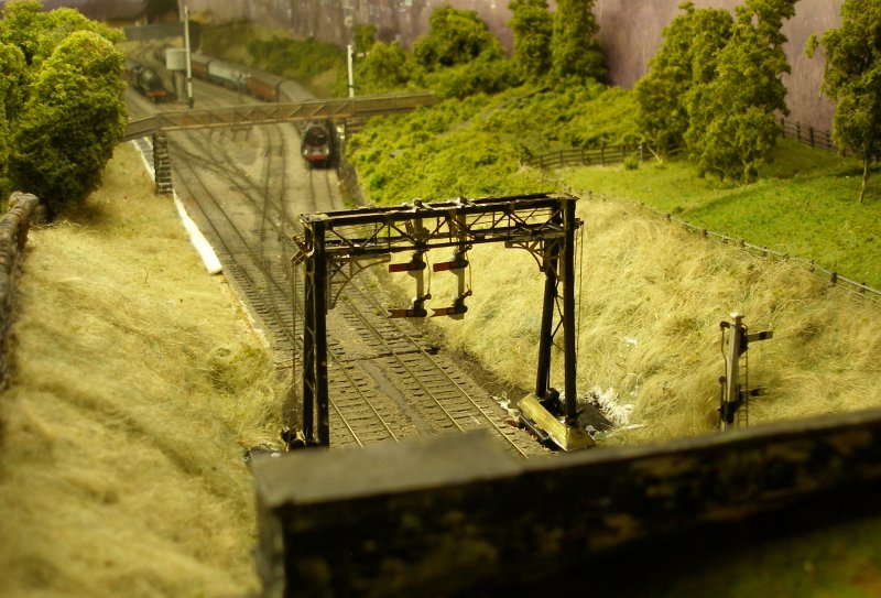
Finally, a view to give a sense of how the final scene will appear. This now accounts for all the main running signals, but there are still three sets of ground discs still required for the full signalling scheme - and also in the middle distance two sets of detonator placing gear!
The next stage is to create the sides and base of the pocket. The base plate is a piece of ply, with spacers - also cut from the same ply - placed between the underside of the baseboard and the baseplate. All mating surfaces had woodglue applied, and then assembled in situ, with a spare piece of 2" x 1" proped up underneath to keep the assembly in place whilst the glue dries. Note the gap left at the back of the pocket through which the wiring will be fed.
And now with the signal gantry tried in the pockets for size. Hopefully the part of the Hornby base protruding into the embankment side will 'disappear' with the application of fresh hanging basket liner.

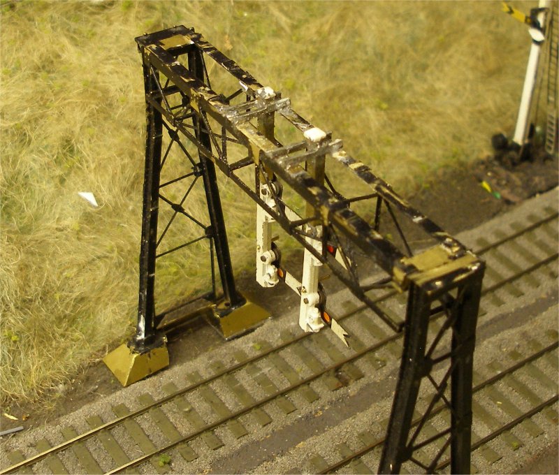
The NJ International signal bridge originally had a wooden platform across the top of the bridge. This was removed and retained. Study of the prototype suggested it needed a platform with a width of three boards, whereas the original brass item was four planks. The platform was accordingly trimmed for width, and shortened to span the distance between the left-hand upright and the second doll.
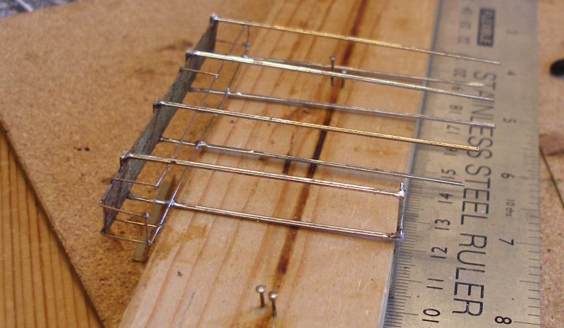
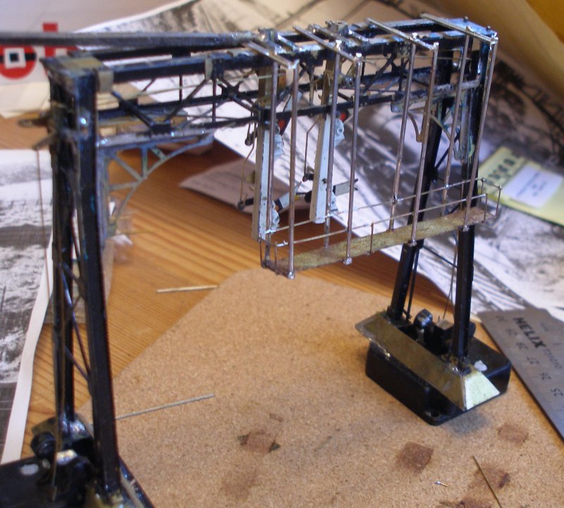
The images below show the first uprights fastened in place, and the hand rails tacked round four sides of the platform, with a gap left access from the ladder.
Having reviewed the work so far, the uprights formed of bullhead rail are too prominent, so a re-think is required.
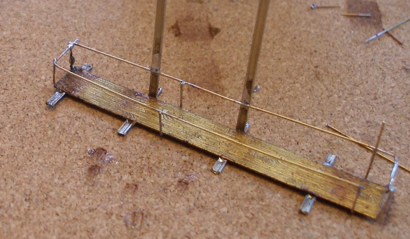
Although not shown in the above photos, the track circuit diamonds have also been added to the dolls.
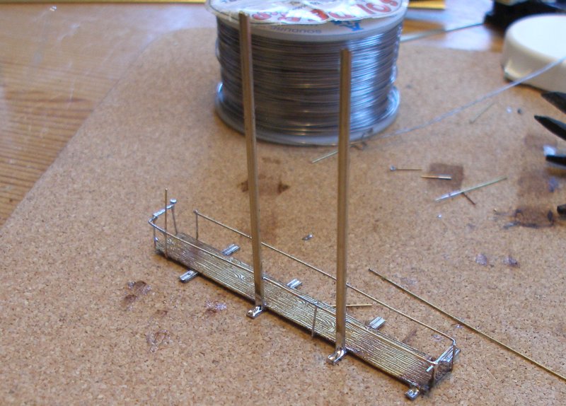
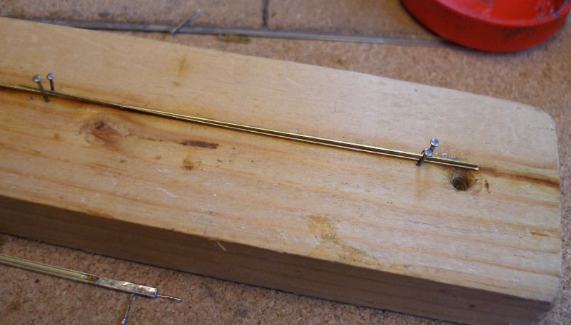
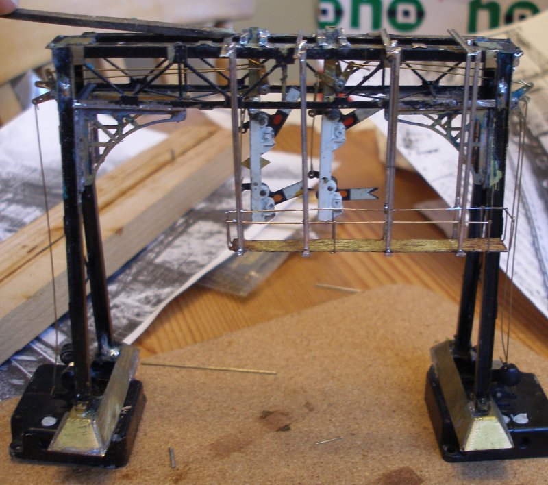
The bull head rail used to form the first few uprights connecting the platform with the top of the crossbeam looked far too large, and therefore thinner material was created soldering to pieces of 0.7 mm straight brass wire together in a simple jig. The photo shows the jig, with two pieces of dis-similar wire dropped in merely to illustrate the process.
Fast forward about an hour and eight uprights have been created and soldered in place.
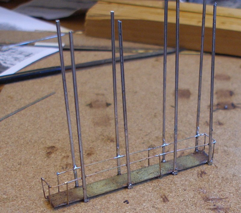
Now the cross beams are soldered to the tops of the uprights, again reverting to bullhead rail.
These proved very quick to fit, and here is the completed platform and supporting structure.
Finally, the complete platform was offered up the rear of the gantry to check the fit.
The platform is looking a tad low in relation to the bottom of the doll, but this will be a quick job to fix. The ladder still needs to be fettled and fixed.
Back blinders will be needed, as the rear of the signal is visible from the signal box. Before the access platform is permanently fixed, the lamps will need to be painted and the signal transfers added.
Finally, the electrical wires will need to be soldered to the tabs on the bottom of the two bases, and the whole inserted into the layout, and the units wired to the DCC accessory decoder.
And there things remained for the next five and half years! Not apparent in the above dialogue was that it was impossible to solder the top of the two dolls to the main girder structure without unsoldering the original diagonal struts.
It was apparent that a glue or similar would be a better option, but at the time I didn't think Araldite would be strong or durable enough.
Fast forward 5.5 years and I have discovered JB Weld. This is marketed as a two-part resin-like product that claims to rival metal when set.
So on 6 August 2022 the draw in which the unfinished and unloved gallows had resided undeserved was finally pulled out and put on the workbench.
One doll was solid and correctly aligned but the second was loose and wobbled around. A series of blocks and packing were placed under the loose doll until it sat level with its friend. JB Weld was then carefully applied around the top of the doll to secure it to the cross bracing and main girder assembly.
Left overnight and in the morning the doll was firmly affixed.
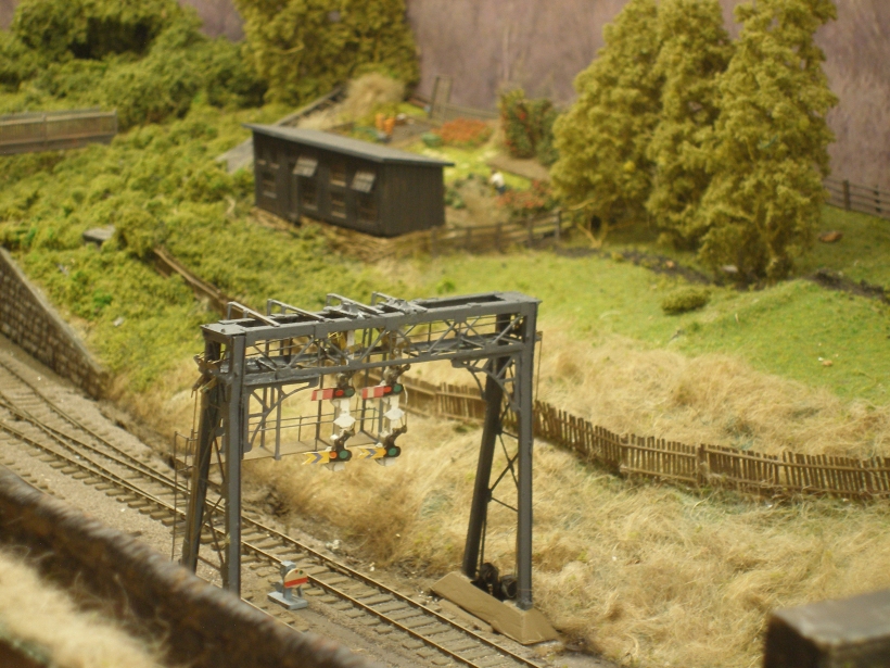
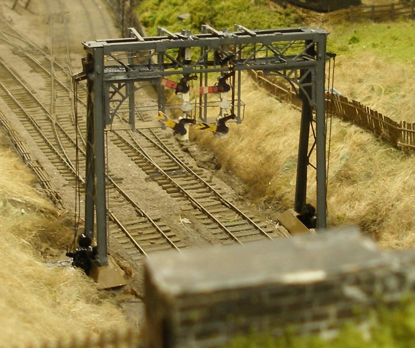
It just remained to paint the main girder work a dark grey and then locate the signal on the layout. In the intervening 5.5 years I had realised that the gallows needed to be closer to the junction and further away from the tunnel mouth, and so the original pocket for the operating mechanism were filled in.
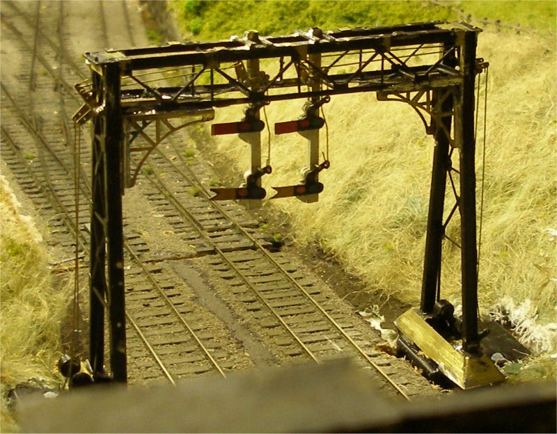
New holes were cut to take the operating mechanisms on either side of the tracks, and the nearly completed assembly finally positioned on the layout.
 .
.
Note: The king points have been subsequently relaind using the new PECO (tm) OO Bullhead GWR-style points and single slip with a significant improvement in both appearance and running.
As forecast over six years ago (!) the only practical way to wire up the signal was to use the five stubs that present on the Bakelite base plate. I had thought that these were solder pads, but in fact they are the brass bases of the screw terminals. No matter, they are eminently receptive to being tinned with the soldering iron, and the wiring up took less than 10 minutes.
It is worth noting that the individual solenoids are arranged east to west rather than north to south. So the two tabs either side of the centre common return are one solenoid, and the two on their own are for the other solenoid.
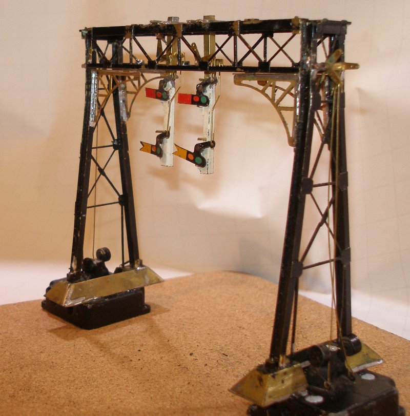
Finally, some effort has been put into the signal arms. I have used the transfers produced for the MSE frets and then cut-and-shut to produce the correct configuration. The HD arms are slightly longer that the MSE brass arms, and so at this stage I am considering drawing a set of transfers exclusively for the Hornby Dublo signals, and then add a couple of arms to the sheet for my shortened Hall Royd arms.
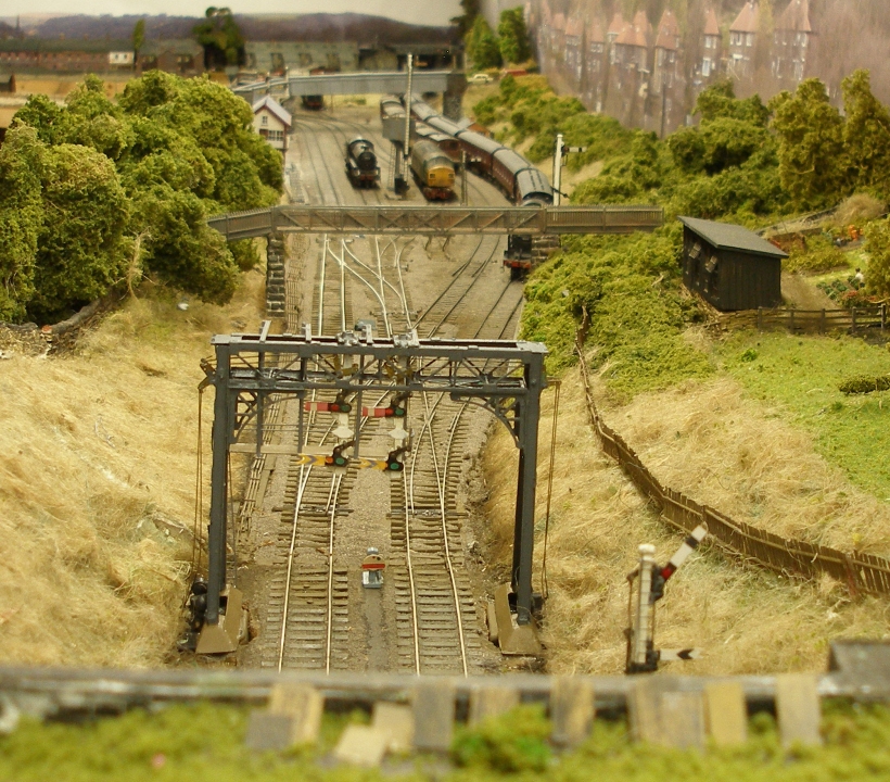
And finally over the finish line! Installed, wired-up and programmed.
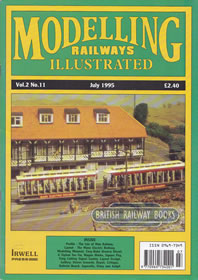
Finally, I had kept - in anticipation of this build - the July 1995 issue of 'Modelling Railway Illustrated' in which Iain Rice detailed the construction of the Tring Cutting Signal Gantry.
On digging this out, and looking at the BR infrastructure photos of the original, the penny finally dropped. The metal portal structure at Millwood Tunnel is very likely a LNWR one, installed sometime after the signalling departments of the LYR and LNWR merged in 1922. Indeed, LNWR pattern arms also appeared elsewhere on the Calder Valley at about this time, notably the Down Bay bracket at Brighouse.
In the article Iain gave some particularly relevant advice on the creation of the bearings within the trusses, recommending that they be formed from Mercontrol brass tubing or similar, so that the bearings rotate easily but have minimal slack in their movement.
My conclusion is that this signal was originally a classic LYR wooden structure, as appeared elsewhere on the system, and that the signal being modelled is the early LMS replacement.

Copyright J K Wallace, t/a 'Hall Royd Junction' 2013-2023 email: Hall Royd Junction
7 Portobello Close, Chesham, Bucks. HP5 2PL, UK
tel: +44 (0)7513 412880