
Signals - First fix
Looking over the parapet of a bridge at a piece of railway line, it is the signals and the signal box that tell you who the owning railway company is, or did, in the age of steam and the semaphore signal.
It was always the intention that Hall Royd Junction would be fully signalled, and by modelling an actual section of railway, it follows that it should be possible to 'spot' the signals accurately. However, the mechanisms to operate the points have to also co-exist with those required to operate the signals.
The construction of the layout started in December 2012 with the assembly of the baseboards. However, despite a lifetime of railway modelling, much of the intervening four years has been taken up with much research and development.
The first major decision was to adopt DCC. This offered the advantage of being able to control both trains and accessories (signals and points) from a single throttle, but was also one of the steeper learning curves.
The original DCC control system was the Lenz compact (the original Lenz starter system). There were three problems using DCC for the accessories. Firstly, changing points, etc with the Lenz was cumbersome, requiring a lot of button pushing. Secondly, the cost of the chipping of the locos was expensive, and thought was given to alternative ways of working the points and signals to reduce the initial expenditure. Finally, two accessory decoders were purchased to assess the working of accessories with DCC, and an immediate problem was that a separate power supply was required to throw any solenoids involved.
A couple of Tortoise motors had also been purchased to assess these for more general deployment, and whilst 'only two wires' is true for basic train operation, it was starting to look as if there would need to be independent 12 volt DC and 16 volt AC supplies to work these accessories.
After playing around with a variety of solenoid drives for the points, two conventional DC control panels were created, one of which was fully wired and commissioned.
However, during this process a decision was made to work the points with piano wire rods, as described in an issue of Hornby magazine. As the key junction is grouped on one baseboard, this low-cost solution allows for the rapid switching of points. This then left the issue of how to create and operate the signals.
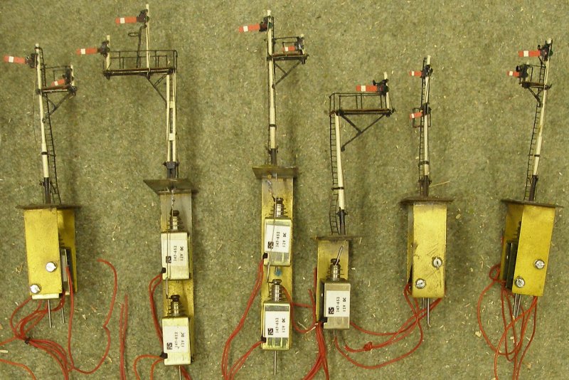
For the original freelance layout, a set of signals were commissioned from Little Jem models. These were LMS/BR upper quadrant signals on tubular posts. Although nicely made, there were some issues with the build such as the signal ladders flexing and the use of signal ladder strip to create the supporting brackets. These models are electrically operated using the very reliable RS347-652 coils, so effectively a 12v DC electro-magnet. This therefore requires a separate power supply. It my current DCC set-up I am attempting to power everything from the bus, and these need an independent supply. Worse, they match none of the signal types required for Hall Royd Junction.
Servos are the current popular solution for signals, as they can be programmed to create a realistic 'bounce' when the arm is returned to the 'on' position. Although the servos themselves are relatively small, many modellers use a wooden bracket to secure the servo under the baseboard. With a fair number of signals required, a more compact way of electrifying the signals was required.
DCC Concepts have also introduced their Cobalt accessory decoder which featured a capacitor on each channel. This meant that for the first time solenoids could be reliably worked from the traction bus, and the need for a separate 16 volt AC supply was dispensed with. For Peco points, it is also worth noting that Gaugemaster have also introduced a DCC solenoid unit.
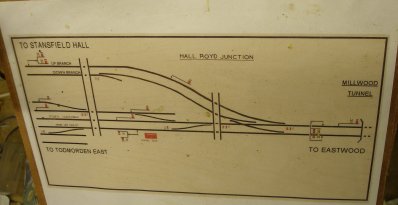
Hall Royd is on the Lancashire and Yorkshire Railway's Calder Valley main line, and in the early 1960s there were still a number of L&YR signal posts in use. Of the seven signals to be modelled (excluding the ground discs), four had wooden posts, including a bracket signal.
Looking for an initial fix, I was struck by the similarity of the Hornby Dublo semaphore signals to prototype L&Y posts fitted with upper quadrant arms. Given that Hornby was based in Liverpool, the obvious local prototypes were either LNWR or LYR - and they certainly are not LNWR!
There is also a steady supply of these electrically worked signals offered as 'spares or repairs' on eBay. There are two types: one or two armed versions, which in turn are offered as the classic Home/Distant combination, or as a two-doll, two-arm bracket signal.
The following narrative records the state of the signalling as at 23 November 2016.
In the Hall Royd area there are two double armed signals on shorter posts, and these lent themselves to a quick upgrade.
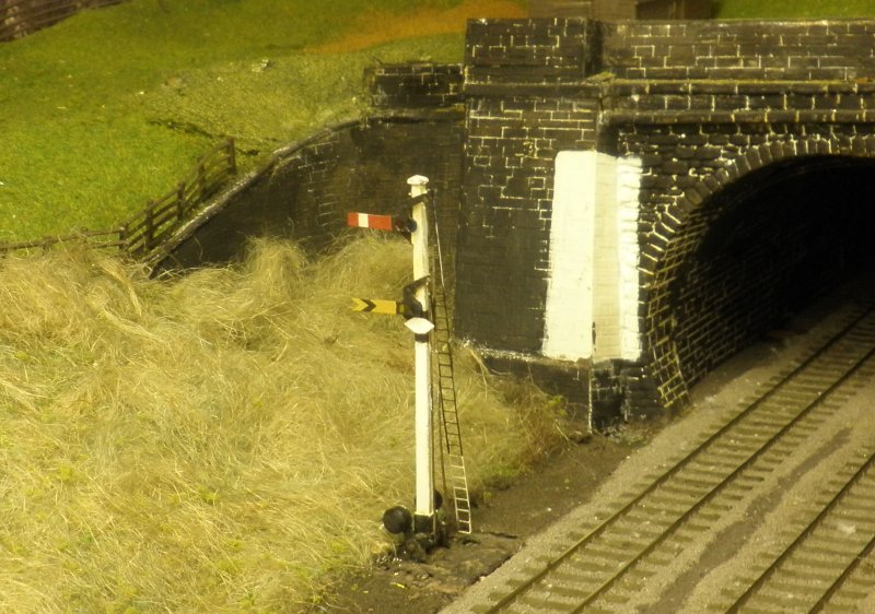
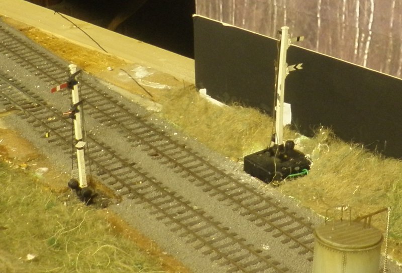
Hall Royd Junction signals 10 and 11 are located at the mouth of Millwood Tunnel and is fashioned from a Hornby Dublo Home/Distant signal. The whitened sighting panel painted onto the tunnel stonework is still visible in 2016. This particular example has been re-armed using MSE etches, with track circuiting diamond and ladder added.
The far end of the layout technically ends at Stansfield Hall Junction. The first signal encountered is the Home and calling on signal, and this is where the layout starts to deviate from the prototype. The point beyond the signal gives access to the return loop whereas on the real thing there was a trailing junction allowing trains from the Manchester direction to head towards Copy Pit and Burnley. The calling arm was for when the banking engine needed to be 'called forward' to bank a train which would have come to a stand beyond the Junction and was awaiting a banker. This would have been a relatively rare movement, as normally the bankers lived in their dedicated sidings located to the left of the signal.
The Home and Distant combo on the other track is an original, unmodified Hornby Dublo item. The distant arm represents Hall Royd's lever #3, and should be on Stansfield's Hall bracket signal. It is a quick fix for now to allow trains to be correctly signalled from Stansfield to Hall Royd.
Hall Royd had a bracket signal controlling access to the Up loop. This was removed in late 1966, but was a classic LYR post with four upper quadrant arms.
The two images below show an incomplete model, but the location of the railings - still to be finished - can be seen.
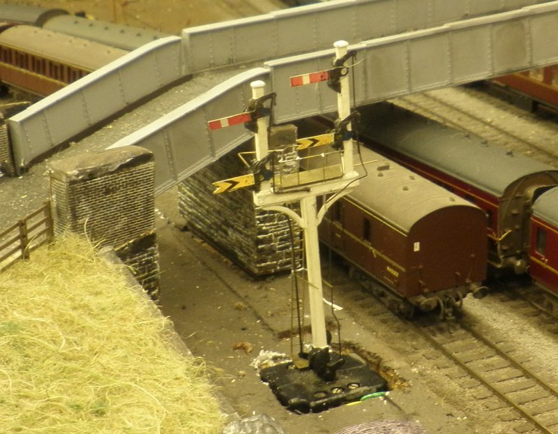
The right hand doll has two arms which are co-acting, so that both arms work together. On the left hand doll only the Home arm is worked, and so the Distant arm is permanently fixed in the 'on' position.
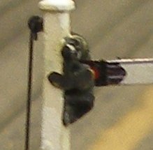
The weakness of the Hornby Dublo design is that the operating arm attached to the spectacle plate is over scale. This can be re-worked, with new holes drilled in both the spectacle plate and the balance weight lever, but this development will form the second phase of signal development. However, it is possible to fix a back blinder to the existing spindle using superglue, as shown in the image below. Note also the use of Hall Royd's own signal transfers available on this site.
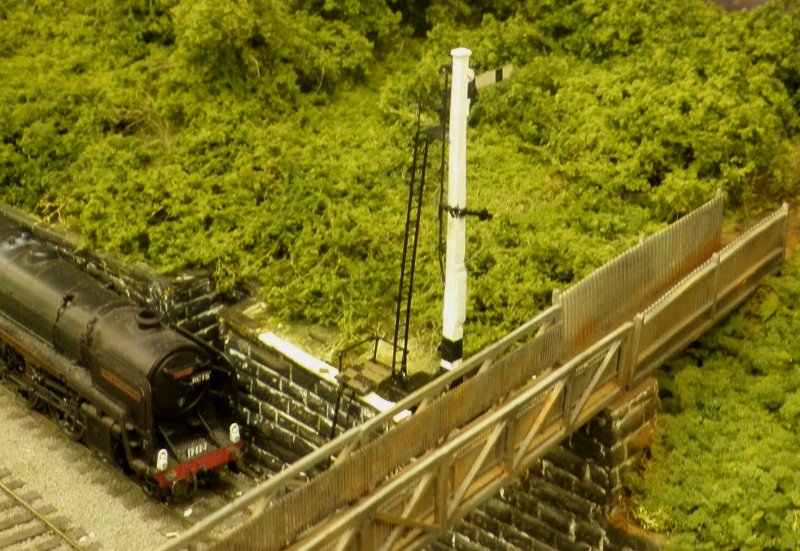
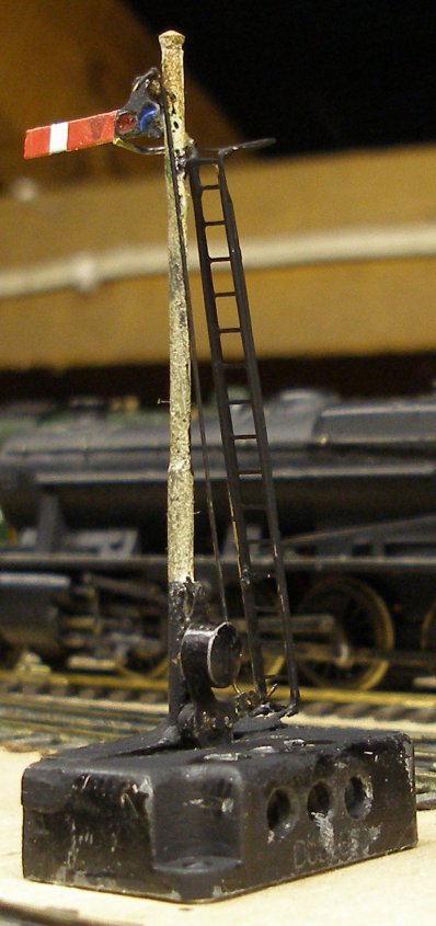
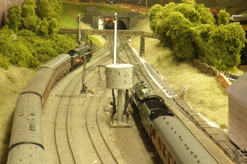
Signal 7 is always on the edge of photographs, and the first attempt to model it proved to be just plain wrong! There is an recess in the retaining wall which seems to have been created for a signal, and into which BR placed a tubular post in late 1966 (this can be seen to the right of the loco smokebox in the photo below). However, careful examination of the photos - and some critical input from L&YRS Signalling Steward Chris Littleworth - established that what appeared to be a tall wooden post placed at track level was, in fact, a shorter post placed on top of the retaining wall. The following photos show the current state of affairs, with the retaining wall still to be restored after removing the original signal.
As now reflected by the model, the access ladder was located at the front of the post, with the balance weight half way up the post, and located at the rear of the post. Access for the lamp man at track level was a two stage affair, with a metal ladder up the face of the retaining wall terminating at a platform on the top of the wall. The signal ladder proper then rose from this platform, as shown on the model.
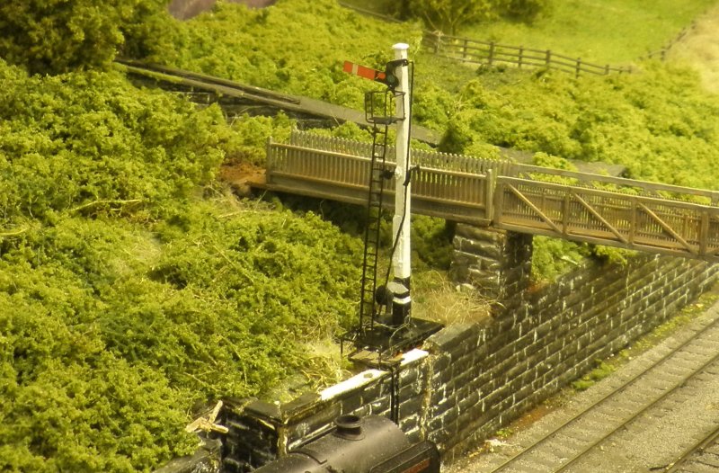
This signal shows an interim method of fixing two halves of a post. To get the post close to the wall, the mechanism had to be rotated through 90 degrees, and then a section cut off the mechanism housing (the bit not containing the coils). Attempting to join the two sections using a rod inserted into holes drilled vertically up and down the two sections of post failed, as for whatever reason, I couldn't drill this particular post. So the two sections where joined using a section of brass troughing. This was an unhappy union, and a revised method was required - see below.
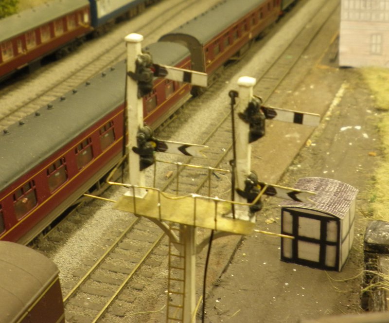
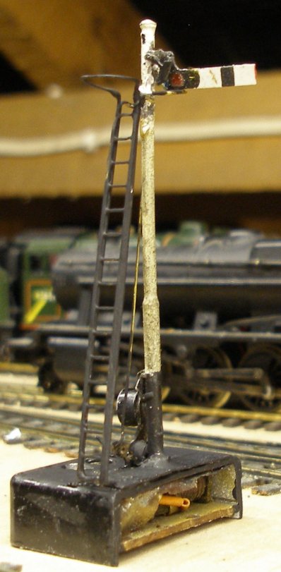
Signal 3 is a particularly tall signal, as it had to be sighted by Down trains passing Todmorden East over a substantial metal road bridge. The prototype had a lattice post, but for expediency, the original L&YR wooden post has been modelled for now. This time the post has been cut, the sides filed approximately 1 cm to form a peg, and then the two ends inserted into 5/32 inches square brass square tube. The join at the bottom of the post has been minimized by making it the division between the black and white painted parts of the post.
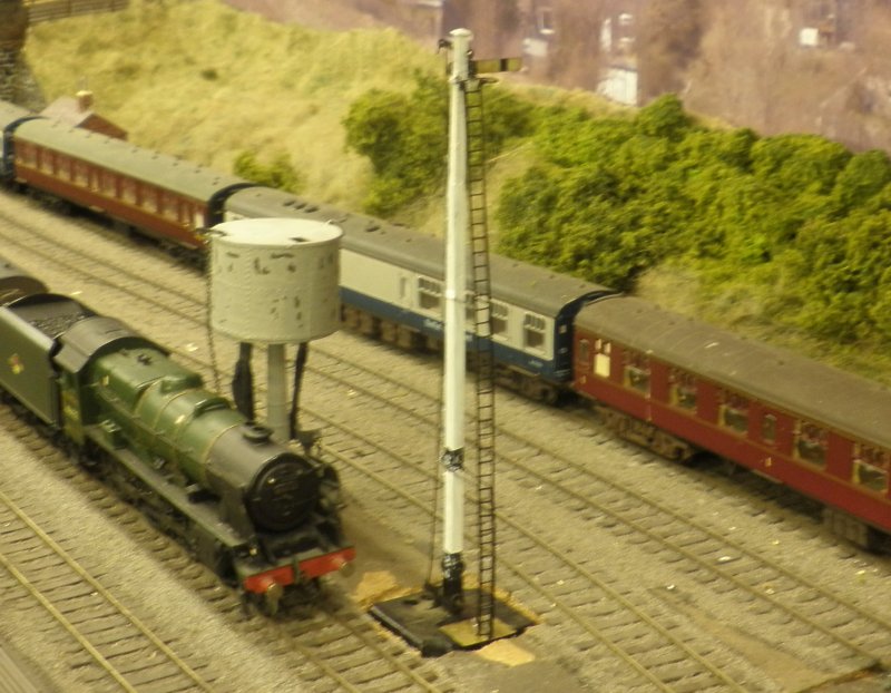
In the right foreground is signal 5; a short tubular post BR upper quadrant signal. This is one of the earliest BR signals installed in the area, being here as early as 1954.This is an MSE signal mounted on the Hornby Dublo mechanism. The bottom of the post is soldered to a piece of old brass fret, and then the plate Araladited to the mechanism base.
The engineering sidings had a tall shunting signal to control exit from the sidings (signal 11), and there was a corresponding Home signal (12) - also a BR Upper Quadrant tubular short post - on the Down loop. This has been fashioned from a Dapol signal with MSE arm and worked by a Tortoise motor.
This leaves just one other signal to model which is the signature gallows signal that guarded the junction for Up trains. Although the LYR had a large number of signals under slung to aid visibility under bridges and through tunnels, the one at Hall Royd appeared to be to a unique design - rather reminiscent of one of the portal structures on the Holcome Brook electrification. A brass gantry was sourced from the US to form the basis of the model. It is close, but not a totally accurate representation.
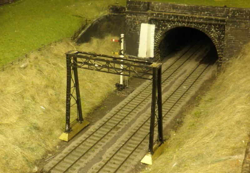
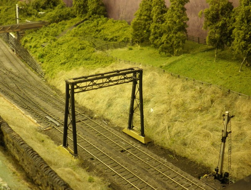
It will need considerable effort to create the two dolls and four arms of the original. It came painted black, although photographic evidence shows that the gantry was originally painted white but it took the full force of hard working Up trains, and was permanently coated in a layer of soot, so appears black in the majority of photos.
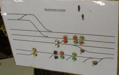
All the signals shown are now fully working and are numbered as per the original signal box diagram.
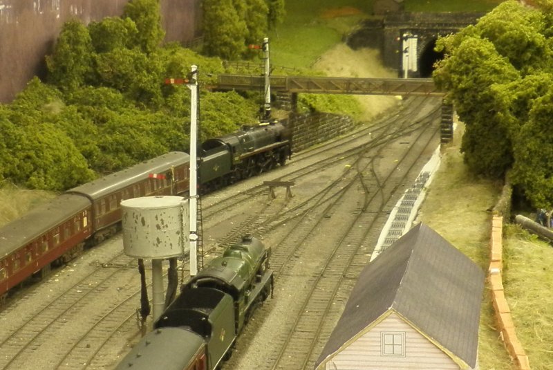
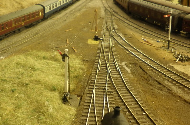
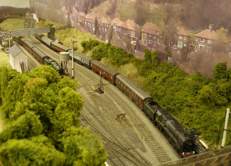
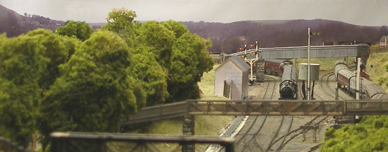
The Calder Valley route was a succession of loops and double track sections conveying a succession of expresses, locals and slow-moving freight and mineral trains. This view shows that something has gone horribly wrong in the Leeds direction, with a returning excursion from Blackpool held on the Copy Pit line, whilst the Scot-hauled afternoon express from Southport bound for Bradford has also ground to a halt. With all signals 'on' and two trains standing, it's not looking good. Part of the problem might be the incomplete point rodding seen running down the right hand side of the tracks.
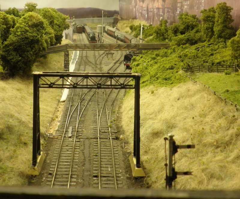
The above image shows all the signals discussed with the exception of the advanced starter at the mouth of Millwood Tunnel and the gallows signal which are below and behind the camera. However this does illustrate an unusual aspect of the layout, it that the Clan-hauled special on the right hand track will be signalled past three signals, two of which incorporate distant arms. It is unusual to correctly place and space distant signals, and it is nice to be able to portray this aspect of railway operation correctly.
The NCE Powercab allows the operation of individual accessories, and it also incorporates an accessory macro. This feature allows up to 16 'macros' to be set, so allowing both points and signals to be pulled off for a particular route. The plan would now to have a macro which pulls off signals 3 & 4 (in the far distance), signal 7 (next to the loco) and signal 9 (the Home next to the tunnel mouth) in one press, and then pull the distant signal arm 10 off as the train approaches, suggesting that the intermediate block towards Eastwood has just cleared.
23 November 2016
Click here for detail construction notes for the Hall Royd Signal Gantry.
Copyright J K Wallace, t/a 'Hall Royd Junction' 2013-2023 email: Hall Royd Junction
7 Portobello Close, Chesham, Bucks. HP5 2PL, UK
tel: +44 (0)7513 412880